Top Flite TOPA0300 User Manual
Page 17
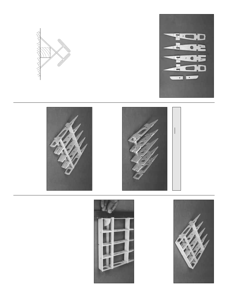
❏
3. La
y out
both sets
of balsa Ribs
W-
2
and
W-
3
, ply Doub
lers
W
-2B
and
W
-2C
, and the ply
Wing Bolt Plates
e
xactl
y
as sho
wn in the photo
.
This w
a
y y
o
u w
on’t assemb
le tw
o r
ight or tw
o left
sides
.
Glue the Doub
lers to the Ribs and laminate
the tw
o pairs of Wing Bolt Plates with
30-Min
ute Epo
xy
. After the epo
xy has cured, test
fit the Wing Bolt Plates into the slots at the aft end
of W
-2 and W
-3. Mak
e
slight adjustments to the
slots if required, b
ut don’t mak
e the fit too loose
as this is a cr
itical area f
or a nice tight bond.
❏
4. Attach the wing plan (the par
t sho
wing the
center section) to a flat b
uilding board and co
v
e
r
it with w
a
x
ed paper
.
Cutting apar
t the wing panel
sections of the plan mak
es handling easier
.
❏
5. Locate the 3/8” x 3/8” x 20” bass
w
o
od
Center Spar
. Cut tw
o 9-1/4” pieces from it. Pin
one of the 3/8” x 3/8” x 9-1/4” bass
w
ood
Center
Spar
s
to the plan using the method sho
wn in the
sk
etch. The Center Spar is a little longer than
actually needed to allo
w f
or the dihedr
al angle at
W
-3. It will be tr
immed to siz
e later
.
❏
6. P
osition r
ib
W-
1
and r
ib assemb
lies
W-
2
and
W-
3
on the Center Spar with the
jig tabs
touc
hing the plan
. Be sure that the ply doub
lers
are f
acing the correct direction.
❏
7. Inser
t (without gluing) the die-cut 1/8” balsa
Center Aft Spar
into the slots abo
v
e
the jig tabs
.
Inser
t the second bass
w
ood Center Spar into
the f
orw
ard r
ib notches
. Mak
e sure that both
Spars are flush with the upper edge of the r
ibs
.
❏
8. Inter
loc
k the 1/8” die-cut ply
Center LE
with
the tabs on the LE of r
ibs W
-3 and W
-1.
❏
9. Study the str
ucture
. Are all par
ts o
v
er their
respectiv
e locations on the plans and in align-
ment? If not,
lightl
y
use fine g
rit sandpaper to
adjust the fit.
Don
’t reac
h f
o
r the CA y
et!
❏
10. Mak
e
sure the W
-3 r
ibs are flush with the
Aft Spar and the Center LE. Use the 1/8” die-cut
ply
Dihedral Gaug
e
on the
inside
of the W
-3
ribs at the f
orw
ard Spars to set the r
ibs angle at
this location. Hold a str
aightedge alongside the
W
-3’
s to chec
k f
or str
aightness
.
❏
11. When y
ou are sure that e
v
er
ything is
str
aight and tr
ue (sight do
wn the TE and shim
an
y lo
w r
ibs with f
olded paper under the jig tabs)
wic
k thin CA into e
ver
y joint
. Hold the LE and
W
-3’
s in tight contact f
or a f
e
w seconds to allo
w
the CA to w
o
rk
. F
ollo
w the initial gluing b
y
apply-
ing a fillet of medium CA around the joints
.
Isn’t inter
loc
king constr
uction g
reat?!
NO
TE: Do not
use an
y CA until step 11.
17