Finishing, Install wing struts and fairings – Top Flite TOPA0300 User Manual
Page 47
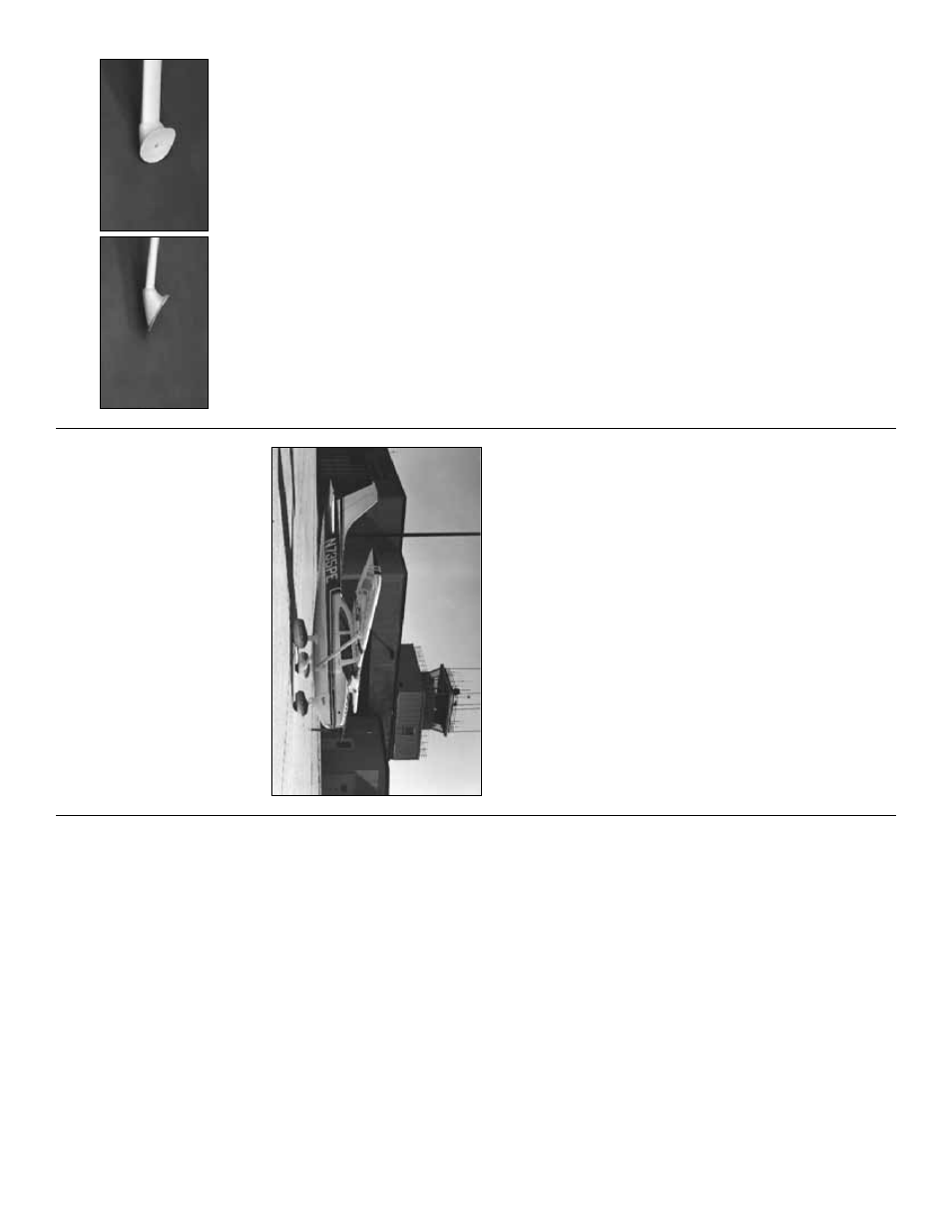
NO
TE: See the wing plan f
o
r a vie
w
of the
strut ends.
❏❏
1. P
o
k
e
a T
-pin through the hole y
ou dr
illed
in the Wing Str
ut Mounting b
loc
k out through the
Fuse side
. Remember? Y
ou glued them behind
F-2 at the lo
w
er cor
ner of the Fuse
.
❏❏
2. Measure and cut tw
o shaped Wing Str
uts
to fit betw
een the pin points and the Str
u
t
attachment b
loc
ks b
u
ried in the wing. Be
v
el the
tw
o ends to fit closely to the Wing and the Fuse
.
❏❏
3. T
rim the ABS Wing Str
ut F
air
ings to the
cut lines
. Cut an airf
oil shape to match the Str
ut
in the ends of a pair of F
air
ings
. Slide the
F
air
ings o
v
er the Str
ut and chec
k the fit betw
een
the Wing and the Fuse
. Use a round file or
Moto-T
ool and sanding dr
um to shape the
outside ends of the F
air
ings to b
lend with the
Fuse and the Wing.
❏❏
4. Center the lo
w
er F
air
ing o
v
er the pin
point and tape it in position around the edges
.
While holding the Str
ut in appro
ximately the
correct position, tac
k glue the lo
w
er F
air
ing to it
with a drop or tw
o of CA.
❏❏
5. Center the upper F
air
ing and Str
ut o
v
er
the mar
k y
o
u made dur
ing “Wing Constr
uction”,
then tac
k glue it to the Str
ut.
❏❏
6. While holding the Str
u
t in a vise (or
propped up so it can’t f
all o
v
er) fill the F
air
ing
ca
vity to the br
im with a 30-Min
ute Epo
xy and
microballoon mixture
. When the epo
xy has
cured, fill the other end in the same manner
.
❏❏
7. Gr
ind or file the epo
xy filler to match the
Fuse and Wing contours
.
❏❏
8. T
ape the Str
ut assemb
ly in position.
Carefully dr
ill a 1/16” diameter hole in the
mounting b
loc
k, per
pendicular to the F
air
ing. If
y
ou miss the Mounting Bloc
k, adjust the dr
ill
angle and tr
y again. Enlarge the correct hole in
only the F
a
ir
ing to 1/8”. Dr
ill a countersink
recess about 1/8” deep x 3/16” diameter to
accept a #4 x 3/4” sheet metal scre
w at each
F
air
ing attachment point.
Near
ly e
v
er
y imperf
ection in y
our w
ood str
ucture
will sho
w through the co
v
e
ring mater
ial;
theref
ore
, bef
ore co
v
e
ring, y
ou should mak
e a
final chec
k of the entire str
ucture
. Fix an
y
“dings
,” then sand the entire str
ucture smooth,
using prog
ressiv
ely finer g
rades of sandpaper
.
Fuel proofing ma
y be done after co
v
e
ring.
❏
1. Fuelproof the engine compar
tment, pa
ying
special attention to the fire
w
all. Either Gre
y
(mix
b
lac
k and white) K&B epo
xy paint or 30-Min
ute
Epo
xy is recommended.
❏
2. Fuelproof an
y e
x
ter
nal e
xposed w
o
od (eg:
flap pushrod e
xits). Matching br
ush-on K&B or
P
erf
ect P
aint w
o
rks nicely here
.
SPECIAL NO
TE: Do not confuse this
pr
ocedure with “c
hec
king the C.G.
” or
“balancing the airplane f
ore and aft.
” That
ver
y impor
tant step will be co
vered later in
the man
ual.
No
w that y
ou ha
v
e
the basic airfr
ame near
ly
completed, this is a good time to balance the
air
plane
laterall
y
(side-to-side). Here is ho
w to
do it:
❏
1. T
e
mpor
ar
ily attach the wing and engine
(with m
uffler) to the fuselage
.
❏
2. With the wing le
v
e
l, lift the model b
y
the
engine propeller shaft and the fin post (this ma
y
require tw
o people). Do this se
v
e
ral times
.
❏
3. If one wing alw
a
ys drops when y
ou lift the
model, it means that side is hea
vy
. Balance b
y
gluing w
eight to the other wing tip
.
NO
TE: An airplane that has been laterall
y
balanced will trac
k better in loops and
other maneuver
s
.
Balance the airplane laterall
y
Fuel pr
oofing
Final sanding
FINISHING
Install wing struts and fairings
47