Coc kpit finishing, Install contr ol surface corrugations – Top Flite TOPA0300 User Manual
Page 50
❏
1. Sand the inside of the coc
kpit with 320-g
rit
sandpaper
. T
rue up an
y une
v
en edges in the
coc
kpit area.
❏
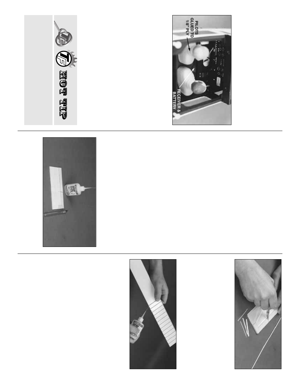
2. Assemb
le and paint y
our pilots
. W
e
used
1/5 scale Williams Brothers pilots which required
a 1” b
loc
k under them to adjust their height. W
e
glued and scre
w
ed our pilots to a piece of 1/8”
light ply (not included) which w
as then scre
w
e
d
to a a couple of b
loc
ks glued to the fuse sides
.
❏
3. P
a
int the inter
ior of the coc
kpit flat b
lac
k.
❏
4. Install the
Instrument P
anel Decal
. It ma
y
be applied directly to the e
xisting panel.
❏
5.
Add an
y other coc
kpit details of y
our
choosing at this time
.
❏
6. T
rim the
Fr
ont Windshield
to the
cut-lines
then glue it to the model. W
e
recommend using
RC-56 glue or 6-Min
ute Epo
xy to glue on the
windshield, b
ut if y
ou ha
v
e
a f
a
v
o
rite technique
,
use it. Y
ou should remo
v
e
a small str
ip of
MonoK
ote (if applicab
le) from under the
windshield’
s fr
ame f
or good glue adhesion. Use
masking tape to hold the windshield in place
while the glue sets
.
❏
7. T
rim the
Side Windo
ws
to fit the openings
on both sides of the Cabin. Be sure to lea
v
e
about 1/8” e
xtr
a plastic around the per
imeter f
o
r
gluing. T
est fit the Windo
ws and tr
im the edges
as necessar
y.
Glue them to the inside of the
Cabin Windo
w F
rame with RC-56 glue or epo
xy
.
❏
1. W
e
made a cutting jig out of scr
ap ply to aid
in tr
imming the ABS e
x
tr
usions to the correct
length f
or each surf
ace
.
❏
2. Cut enough pieces of a specific length to
do both sides of each control surf
ace
, then
change the jig f
or the ne
xt length. K
eep each
piece close to the correct length (no more than
1/8”) to a
v
oid w
aste
.
❏
3. Use the plans as a guide to dr
a
w
the
location of each corr
ugation on the control
surf
ace
, then, while holding the corr
ugation in
position, place one drop of thin CA into the
opening at each end.
❏
4. T
rim off an
y e
xcess with a
single-edg
e
razor b
lade
.
J
ust f
o
r the record, the patience required to do
this par
t of the model will be re
w
arded b
y
an
e
xtremely realistic finish and a lot of “oohs” and
“ahs” at the field.
Install contr
ol surface corrugations
F
or best results
, stic
k the instr
ument decal to a
scr
ap piece of 1/32” to 1/16” plyw
ood, tr
im it to
shape
, then use spots of self-adhesiv
e V
elcro
(hook and loop) to hold it in place
.
Coc
kpit finishing
50