Balance y our model, Contr ol surf a ce thr o w s – Top Flite TOPA0300 User Manual
Page 52
❏
3. W
e
installed a pushrod tube (not included
in the kit) along the bottom inside surf
ace of the
fuse
, to ser
v
e
as a conduit f
or the antenna. The
antenna w
as then inser
ted and pushed to the aft
end of the fuse
.
❏
4. The Receiv
er and Batter
y ma
y be “w
edged”
in place under the ser
v
o
tr
a
y
with additional
la
y
ers of f
oam r
u
b
ber
.
❏
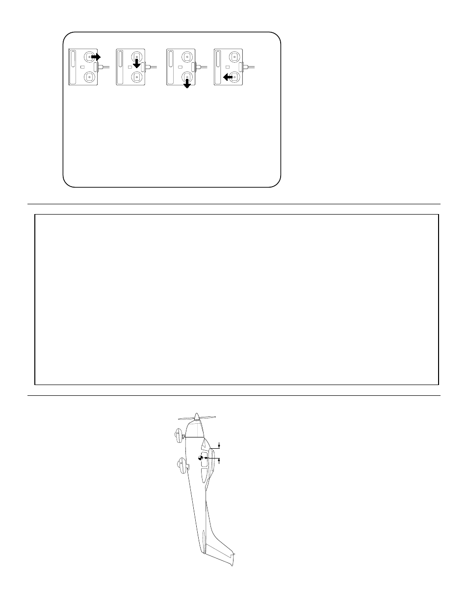
5. Mak
e
sure the control surf
aces mo
v
e
in the
proper direction as illustr
ated in the f
ollo
wing
sk
etches:
❏
6. Adjust y
our pushrod hookups as necessar
y
to pro
vide the control surf
ace mo
v
ements sho
wn.
NO
TE: The surface thr
o
ws and balance f
o
r
this air
craft ha
ve been e
xtensivel
y tested. W
e
are confident that the
y represent the settings
at whic
h the Cessna 182 flies best. Please set
up y
our air
craft to the specifications listed
abo
ve
. If
, after a f
e
w flights, y
ou w
ould like to
adjust the thr
o
ws to suit y
our tastes, that is
fine
. The Cessna 182 has lar
g
e ele
v
ator
s and
does not require m
u
c
h
thr
o
w
. T
oo m
u
c
h
thr
o
w
can f
o
rce the plane into a stall, so
remember
... “More is not better
.”
NO
TE: This section is VER
Y impor
tant and
m
ust NO
T be omitted! A model that is not
pr
operl
y balanced will be unstab
le and
possib
ly unfl
y
a
b
le
.
❏
1. Accur
ately mar
k the balance point on the
bottom of the wing on both sides of the fuselage
.
The balance point is sho
wn on the plan (
CG
),
and is located
4” (102 mm) bac
k fr
om the
leading edg
e at the wing r
oot
as sho
wn in the
sk
etch and on the plans
. This is the balance point
at which y
our model should be balanced f
or y
o
ur
first flights
. Later
, y
ou ma
y wish to e
xper
iment b
y
shifting the balance up to
3/8” f
orwar
d or 1/4”
bac
k
to change the flying char
acter
istics
. Mo
ving
the balance
forwar
d
ma
y impro
v
e
the
smoothness and tr
ac
king, b
ut it ma
y also require
more speed f
or tak
eoff and mak
e it more difficult
CG
4"
Balance y
our model
CONTR
OL SURF
A
CE THR
O
W
S
:
W
e
recommend the f
ollo
wing control surf
ace
thro
ws:
NO
TE:
Thro
ws are measured at the
widest
par
t
of the ele
v
ators
, r
udder
, and ailerons
.
NO
TE: If y
our radio does not ha
ve “dual
rates”, then set up the contr
o
l surfaces
to mo
ve at the high rate thr
o
ws.
ELEV
A
T
OR:
(High Rate)
1-1/16” up
1-1/16” do
wn
(Lo
w Rate)
3/4” up
3/4” do
wn
R
UDDER:
(High Rate)
1” r
ight
1” left
(Lo
w Rate)
5/8” r
ight
5/8” left
AILER
ONS:
(High Rate)
5/8” up
5/8” do
wn
(Lo
w Rate)
1/2” up
1/2” do
wn
FLAPS:
(T
ak
eoff)
1” do
wn
(Landing)
2” do
wn
TRIM MIXING:
If y
our tr
ansmitter is
prog
ra
mmab
le f
or Flap to Ele
v
ator mixing w
e
deter
mined dur
ing our flight tests that attitude
control w
as smoother with 3/16” of
do
wn
Ele
v
ator tr
im at half Flaps and 3/8” of do
wn
ele
v
ator tr
im at full Flaps
.
4-CHANNEL
TRANSMITTER
4-CHANNEL
TRANSMITTER
4-CHANNEL
TRANSMITTER
4-CHANNEL RADIO SETUP
(STANDARD MODE 2)
TRANSMITTER
4-CHANNEL
ELEVATOR MOVES UP
RIGHT AILERON MOVES UP
LEFT AILERON MOVES DOWN
RUDDER MOVES RIGHT
CARBURETOR WIDE OPEN
52