Install nose g ear steering – Top Flite TOPA0300 User Manual
Page 35
❏
11. Chec
k alignment, then glue the die-cut
1/8” ply
Wing Sad
dle Braces
into the notches
on F-2B and F-3B
.
❏
12. Fit the die-cut 1/8” ply rear
Windo
w
Frames
into the notches in F-5B and the Wing
Saddle Br
aces
. The upper ends should protr
ude
abo
v
e
the Wing Saddle Br
ace about 3/32”. Glue
the Rear Windo
w F
rames into position then
lightly sand the protr
uding tips
, lea
ving about
1/16” abo
v
e
the Wing Saddle Br
ace
.
❏
13. Glue the top and bottom die-cut 3/32”
balsa
Cabin Sides
together
.
❏
14. Align both Cabin Sides f
ore and aft on the
Main Str
inger betw
een IP and F-5B
. Fit the
notch at the upper front cor
ner of the Cabin Side
wing roots
to the tabs at the top of F-2B
. Glue
the Cabin Sides to the Main Str
ingers
, F-2B and
F-3B
,
b
ut not to the Wing Sad
dle Brace
.
❏
15. Press do
wn on the middle of the Wing
Saddle Br
ace until it is about 1/16” belo
w the top
edge of the Cabin Side
, then wic
k thin CA along
the seam to hold it in position. When cured, add
a fillet of medium CA to the joint to secure it in
place
.
This depression will allo
w f
or the addition
of F
oam Wing Saddle T
ape and minor
adjustment to the wing’
s alignment if needed.
❏
16. Repeat Step 15 f
or the other side of the
fuse
. Sand the edge of the Cabin Sides flush
with the Rear Windo
w F
rames
.
❏
17. Use 30-Min
u
te Epo
xy to glue the 3/8” x
7/8” x 1” hardw
ood
Wing Bolt Bloc
ks
into the
poc
k
ets of the Wing Saddle Br
aces and to F-3B
.
Mak
e
sure that y
ou obtain a solid bond betw
een
all par
ts
. T
u
rn
the fuse upside do
wn and
ad
d a
fillet of epo
xy
around the edges of the Wing
Bolt Bloc
ks
under
the Wing Saddle Br
aces
.
❏
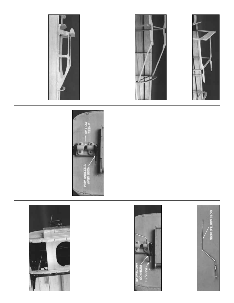
1. Install a
3/16” Wheel Collar and Set
Scre
w
on the Nose Gear Wire
, betw
een the
upper and lo
w
er par
ts of the Nose Gear Bear
ing.
The top end of the Nose Gear Wire m
ust
protr
ude 3/16” abo
v
e
the top of the Bear
ing.
Install the
Nose Gear Steering Arm
on the top
end of the Nose Gear Wire as sho
wn. Use a 6-
32 x 1/4”
Soc
ket Head Cap Scre
w
to secure the
Nose Gear Steer
ing Ar
m in position, angled 1-
1/8” f
orw
ard of F-1 when the wheel’
s axle is
par
allel to F-1.
See plan bottom vie
w f
or angle
.
❏
2. Cut 1/2” from the
threaded end
of the 4-40
x 12”
Nose Wheel Steering Pushr
od
wire
. File
off an
y b
u
rrs from the cut end. Scre
w
a 4-40
He
x
Nut
and
Metal Cle
vis
onto the Pushrod. Use the
patter
n on the plans to bend the Pushrod as
indicated, b
u
t don’t cut off the e
xcess y
et.
❏
3. Dr
ill a 3/32” hole through the outer hole of
the Nose Gear Steer
ing Ar
m. Inser
t the
hea
vy-
duty Scre
w Loc
k Pushr
od Connector
up from
the bottom of the Nose Wheel Steer
ing Ar
m,
then secure it with a Star W
asher
. Inser
t the
unthreaded end of the Pushrod through the
Connector to
w
a
rd F-1. Vie
w
the fuse from abo
v
e
to align the Pushrod with the r
udder ser
v
o
, then
mar
k F-1 using the Pushrod as a punch.
❏
4. Dr
ill a 3/16 hole through F-1 on the mar
k
y
ou just made
.
❏
5. Hook up y
our r
adio and
c
hec
k that the
rud
der ser
v
o
is centered
. Cut the Pushrod to
Install nose g
ear steering
35