Top Flite TOPA0300 User Manual
Page 46
❏❏
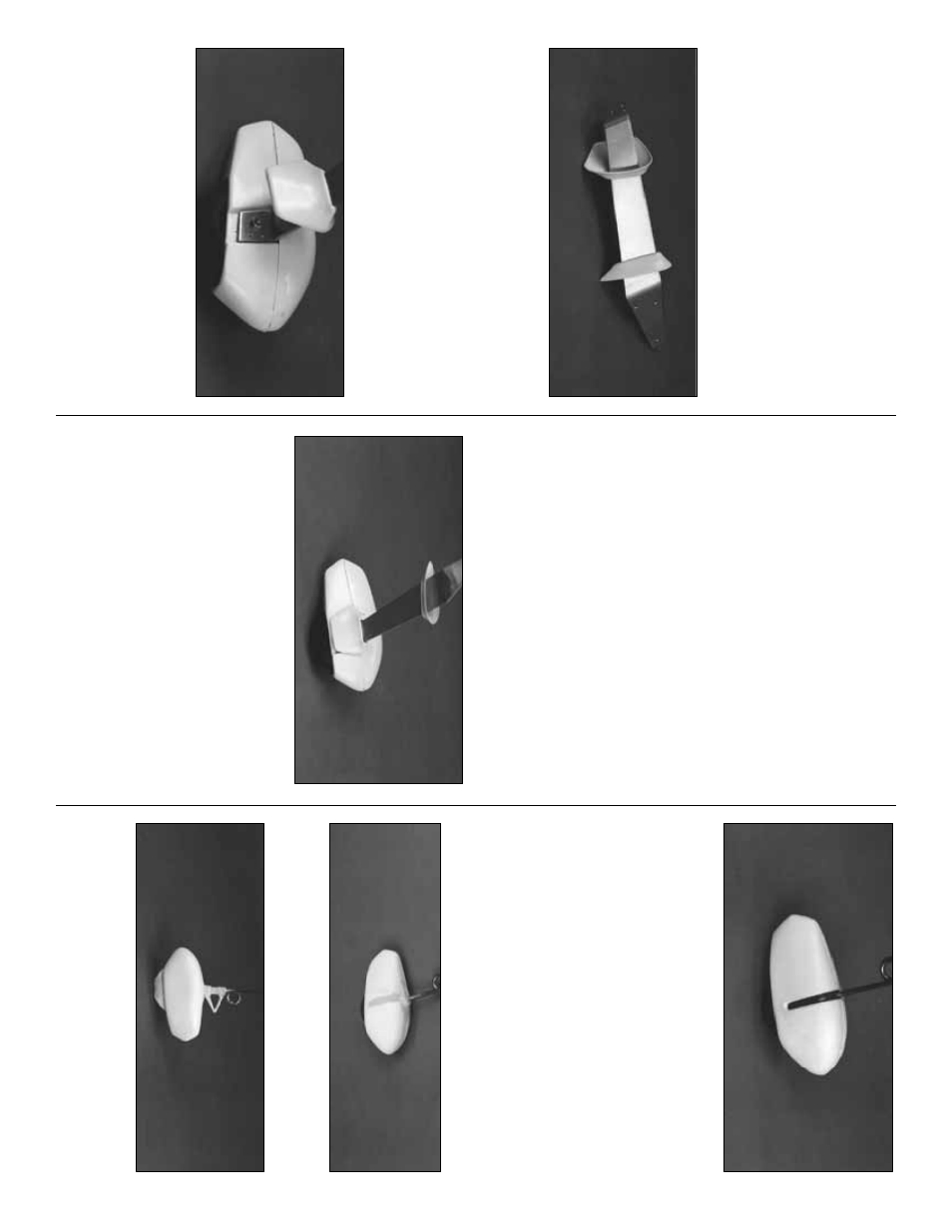
6. Roughen the mating area of both Wheel
P
ant halv
es with coarse sandpaper
. T
ape the
upper half of the Wheel P
ant in position, then
wic
k
thin CA around the seam. Remo
v
e
the tape
and fill the seam with Bondo
®
. Sand the Bondo
when it has hardened.
NO
TE: Remo
v
e the Landing Gear fr
om the
model to do the ne
xt se
veral steps.
❏❏
7. T
rim the ABS upper and lo
w
e
r
Landing
Gear F
a
irings
to the cut lines
. Cut a slot in both
par
ts to fit at the top and bottom of the Landing
Gear as sho
wn. Slide them onto the Landing
Gear str
ut b
ut don’t glue them in position y
et.
❏❏
8. Assemb
le the Axle and 3-1/4” wheel as
sho
wn in the photo
. The He
x Nut should not
inhibit free rotation of the wheel.
❏❏
9. Inser
t the Axle through the hole in the
w
ooden suppor
t assemb
ly
, then scre
w it into the
Landing Gear str
ut. (
Hint:
Gr
ind a scre
wdr
iv
e
r
slot in the threaded end of the axle bolt.) Scre
w
another 8-32 he
x n
ut onto the Axle bolt from the
other side of the Landing Gear str
ut, loc
king the
axle in place
. Chec
k that the wheel still rotates
without binding. Put a drop of thin CA on the
outer he
x n
ut to loc
k it in place
.
❏❏
10. Install the Main Landing Gear
, then
slide the upper F
a
ir
ing into contact with the
Fuse
. Sand the F
air
ing edges to obtain a good fit
with the cur
v
ature of the Fuse
. Put a small
amount of 6-Min
ute Epo
xy
inside the F
airing
where it touc
hes the Landing Gear strut
, then
slide it bac
k into contact with the Fuse
.
Do NO
T
glue the F
a
iring directl
y
to the fuse
as it m
ust
be ab
le to fle
x
with the Landing Gear and also
allo
w y
ou to remo
v
e
the Landing Gear str
ut f
o
r
maintenance if needed.
❏❏
11. Align the bottom edge of the Wheel
P
ants with y
our w
o
rkbench, with the model in a
le
v
el attitude
. Scre
w a #2 x 3/8” sheet metal
scre
w
through the small hole ne
xt to the Axle
into the Wheel P
ant to hold it in alignment.
❏❏
12. Slide the lo
w
er Landing Gear F
air
ing
do
wn until it touches the Wheel P
ant. Wic
k
thin
CA around the edges to attach it to the P
ant. Fill
in the bottom edge recess with Bondo and sand
it smooth.
❏❏
13. The ABS Nose Gear Wheel P
ant
assemb
les in the same manner as the Main
Landing Gear P
ants
, b
u
t has no inner suppor
t
assemb
ly
. Cut out the opening on the bottom f
o
r
the wheel. Dr
ill a 3/16” hole f
or the axle wire
.
❏❏
14. Inser
t the Nose Gear Wire into the axle
hole
. Slide a 3/16” wheel collar onto the wire
from the inside f
ollo
w
ed b
y
a 2-3/4” wheel
follo
w
ed b
y
another wheel collar
. Center the
wheel and tighten the wheel collar set scre
ws
.
Apply a liber
al coating of 6-Min
ute Epo
xy to the
recessed gear wire to hold it in place
.
NO
TE: Bef
ore installing the Nose Gear Wire
c
lean it with rubbing alcohol and r
oughen
the section that will be glued to the wheel
pant bef
ore installing it.
15. Fill the joint seam and the Nose Gear wire
recess with Bondo
®
.
16. OPTIONAL: W
e
added a shor
t section of a
Robar
t dumm
y oleo str
ut to our prototype to giv
e
a more scale appear
ance
.
46