Build the wing – Top Flite TOPA0300 User Manual
Page 16
❏
8. T
rue up all r
udder edges with a sanding b
loc
k.
❏
9. P
osition the r
udder against the TE of the fin
with the top of the r
u
dder
1/32
”
abo
ve the top
of the main bod
y of the fin
. T
ape the fin and
rudder securely together with masking tape
.
NO
TE: Bef
ore pr
oceeding, stud
y the photo
at step 15 to see what y
ou will accomplish
in the ne
xt six steps.
❏
10. T
est fit the 3/4” shaped balsa
Rud
der Tip
on top of the r
udder
. It should b
utt against the
Fin Tip squarely
, and ha
v
e
a clear
ance gap of
1/32” abo
v
e
the fin. Mak
e
adjustments with a
sanding b
loc
k if needed.
❏
11. Use thic
k CA to glue the Rudder Tip to the
rudder
. Be sure that e
v
er
ything is centered
bef
ore the CA cures
.
❏
12. Dr
a
w
a center ref
erence line across the
top of the r
udder and fin b
loc
ks
. A piece of
masking tape stretched across the center of the
b
loc
ks will help y
ou dr
a
w
a f
air
ly str
aight line
.
❏
13. Use a r
a
z
o
r plane and sanding b
loc
k to
shape the top of the fin and r
udder
. F
o
r
scale
realism
, the Rudder Tip should be
slightl
y
wider
than the r
udder
. Apply 4 la
y
ers of masking
tape to each side of the r
udder to pre
v
ent y
o
u
from remo
ving too m
uch mater
ial. The Fin Tip
ma
y be sanded flush with the fin. Round off the
top 3/8” of both the Fin and Rudder Tips
. When
the top is shaped and sanded, remo
v
e
all mask-
ing tape
.
❏
14. Dr
a
w
a center
line on the r
udder’
s LE.
Sand a “V” be
v
el along this line with ref
erence to
the plans f
or the correct angle
. Hinging and
installation of the torque rod will come later in
the assemb
ly process
.
❏
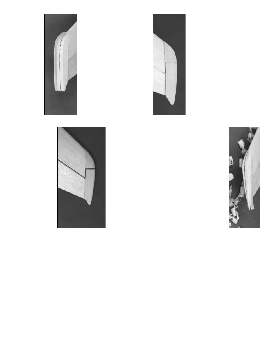
15. Sand a r
adius around the f
orw
ard edge of
the Rudder Tip
. Hold the fin and r
udder together
to chec
k the clear
ance betw
een the Rudder Tip
and the Fin Tip
. Contin
ue sanding the Rudder
Tip r
adius until there is a 1/32” gap betw
een the
tw
o par
ts
.
Oka
y,
the tail f
eathers are more or less com-
plete
, so b
y
no
w y
o
u are on a roll. The stab
looks lik
e the wing f
or a .20-siz
e model, doesn’t
it? W
e’ll b
uild the wing ne
xt so y
ou’ll really
ha
v
e
something to impress y
our b
uddies when the
y
drop in to see “ho
w the ol’ Cessna is doing.
”
NO
TE: The wing panels are b
uilt
“
UPSIDE-
DO
WN
”
on the plans. The jig tabs are
attac
hed to what is, in the end, the T
OP sur-
face of the wing. Since it is the standar
d con-
vention to sho
w the T
op Vie
w of the wing,
and the wing panels are b
uilt upside-do
wn,
the LEFT wing panel is b
uilt o
ver the RIGHT
Wing T
op Vie
w
and vice-ver
sa. This does not
present an
y pr
ob
lems
—
just be sure to b
uild
a left and a right wing.
❏
1. Punch out all the die-cut 3/32” and 1/8”
balsa wing
Ribs
. Smooth out an
y imperf
ections
with sandpaper
. Be sure to k
eep the jig tabs
attached to the r
ibs
.
❏
2. Punch out the 1/8” ply
Doub
ler
s
and
Wing
Bolt Plates
.
Build the center section
B
UILD THE WING
16