4 sbus wiring, 1 calculating wiring distance for sbus modules, Sbus wiring – SilentKnight 5600 User Manual
Page 41
Control Panel Installation
151450
4-9
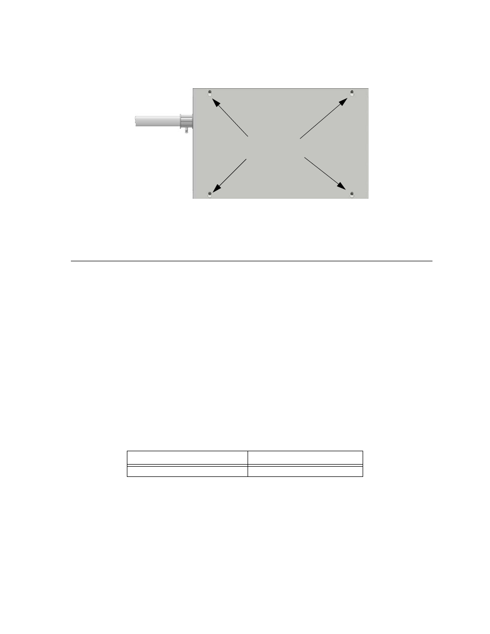
6. Align the cover plate mounting keyhole over the cover mounting screws. See Fig-
ure 4-8.
Figure 4-8 Cover Plate Mounting Keyholes and Cover Mounting Screws Alignment
7. Slide the cover into place and tighten the cover mounting screws. See Figure 4-8.
4.4
SBUS Wiring
This section contains information on calculating SBUS wire distances and the types
of wiring configurations (Class B).
4.4.1
Calculating Wiring distance for SBUS modules
The following instructions will guide you in determining the type of wire and the
maximum wiring distance that can be used with control panel SBUS accessory
modules.
To calculate the wire gauge that must be used to connect SBUS modules to the
control panel, it is necessary to calculate the total worst case current draw for all
modules on a single 4- conductor bus. The total worst case current draw is calculated
by adding the individual worst case currents for each module. The individual worst
case values are shown in the table below.
Note: Total worst case current draw on a single SBUS cannot exceed 500 mA.
After calculating the total worst case current draw, Table 4-1 specifies the maximum
distance the modules can be located from the panel on a single wire run. The table
insures 6.0 volts of line drop maximum. In general, the wire length is limited by
resistance, but for heavier wire gauges, capacitance is the limiting factor.
These cases are marked in the chart with an asterisk (*). Maximum length can never
be more than 6,000 feet, regardless of gauge used. (The formula used to generate
this chart is shown in the note below).
Model Number
Worst Case Current Draw
5635 Remote Fire Annunciator
.04 amps
Cover Plate
Mounting Keyholes