5 board assembly diagram, Board assembly diagram – SilentKnight 5600 User Manual
Page 25
Before You Begin Installing
151450
3-5
3.5
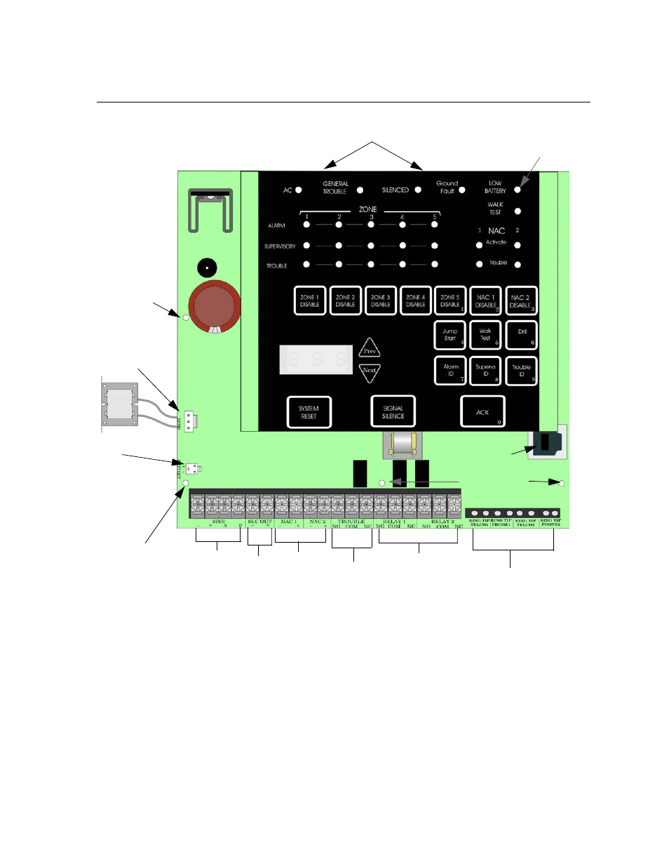
Board Assembly Diagram
Figure 3-2 Model 5600 Assembly
Figure 3-2 shows the 5600 circuit board stack. If you should need to remove the
control board for repair, remove the three mounting screws which hold the control
board in the cabinet, slide out of slot from slide-in standoff. Then lift the control board
off the location mounting pin and out of the cabinet.
Form C
Trouble
On-board
Annunciator
Battery
Connector
AC Power
Input
Form C
Programmable
Relays
AC Power Input
Battery
Connector
24VDC
Ethernet
Programming Port
Mounting
screw
Location
Mounting
Pin
Mounting screws
Slide-In Stand-offs
SBUS
SLC Out NAC/AUX
Power
Circuits
Phone Lines
See also other documents in the category SilentKnight Safety:
- 5104 Digital Alarm Communicator Transmitter 6 Zone (48 pages)
- 5128 Digital Alarm Communicator Transmitter (42 pages)
- 5217 10-Zone Expander for 5208 (2 pages)
- 5220 Direct Connect Module (2 pages)
- 5235 Remote Annunciator for 5208 (2 pages)
- 5280 Status Display Module for 5208 (2 pages)
- 5495 6A Distributed Power Module (52 pages)
- 5496 6A Intelligent Remote Power Supply (38 pages)
- 5499 9A Distributed Power Module (56 pages)
- 5660 Silent Knight Software Suite (28 pages)
- 5670 IntelliKnight Facility Management Software (24 pages)
- 5700 (180 pages)
- 5808 (180 pages)
- 5815RMK Remote Mounting Kit (2 pages)
- 5815XL Signal Circuit Expander (2 pages)
- 5820XL-EVS (236 pages)
- 5824 Serial/Parallel Module (2 pages)
- 5860/5860R Remote Annunciator (2 pages)
- 5865-3/5865-4 Remote LED Annunciator (2 pages)
- 5880 LED Driver Module (2 pages)
- 5883 Relay Interface Board (4 pages)
- 5895XL 6A Intelligent Remote Power Supply (56 pages)
- B200S Intelligent Sounder Base with CO Support (4 pages)
- B200S-LF - Low Frequency Intelligent Sounder Base (4 pages)
- B200SR Sounder Base (4 pages)
- B200SR-LF Low Frequency Intelligent Sounder Base (4 pages)
- B210LP 6 Mounting Base (2 pages)
- B224BI 6 Mounting Base w/Built-in Isolator (2 pages)
- B224RB 6 Mounting Base w/Built-in Relay (4 pages)
- B501 4 Mounting Base (2 pages)
- Central Station Monitoring List (1 page)
- Document Revision History (4 pages)
- EVS (74 pages)
- EVS-CE4 (2 pages)
- EVS-RVM (2 pages)
- EVS-VCM (2 pages)
- FFT (1 page)
- FFT-24 (2 pages)
- FFT-24 Installation (1 page)
- FFT-FPJ (1 page)
- FFT-HSC (1 page)
- FFT-STSS and FFT-STSR (2 pages)
- HFS-D (4 pages)
- HFS-MM (1 page)