Connector and cable pinouts, W.m.d. connectors, Red 3-axis system operation guide – RED 3-AXIS LENS CONTROL SYSTEM User Manual
Page 55
COPYRIGHT © 2014 RED.COM, INC
RED 3-AXIS SYSTEM OPERATION GUIDE
955-0044, REV-D | 55
C
This appendix provides RED 3-Axis Lens Control System pinout information for the Wireless Motor Driver,
Tactical Hand Controller, Lens Control Motor as well as RED
®
connector cables that are used with the system
components.
NOTE: When connecting a cable to a connector, align the key and red marker on the cable connector with the
corresponding key and marker on the device connection.
NOTE: Connector diagram images are for reference only. Diagrams are not to scale.
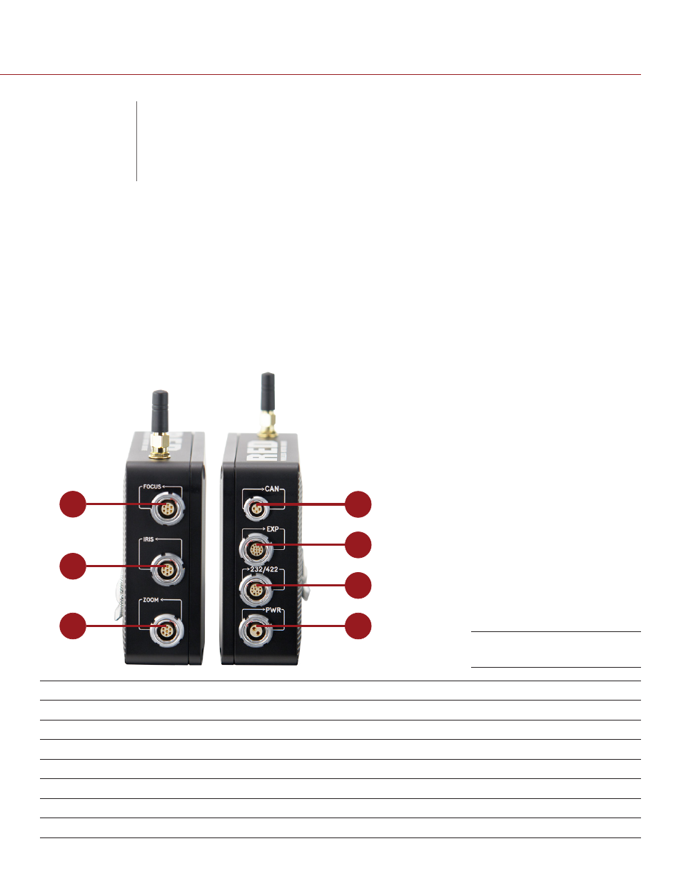
W.M.D. CONNECTORS
1
2
3
4
5
6
7
#
CONNECTOR
CONNECTOR TYPE
CONNECTOR FUNCTION
1
FOCUS
7-pin 1B LEMO
Lens motor drive support; Focus control knob on T.H.C.
2
IRIS
7-pin 1B LEMO
Lens motor drive support; Iris control knob on T.H.C.
3
ZOOM
7-pin 1B LEMO
Lens motor drive support; Zoom control slider on T.H.C.
4
CAN
4-pin 0B LEMO
CAN communication and power for the T.H.C.
5
EXP
14-pin 1B LEMO
Start/Stop, Tally, RS-232, GPIOs
6
232/422
10-pin 1B LEMO
RS-232/422 communication
7
PWR
2-pin 1B LEMO
12 V to 18 V power
W.M.D. Connections
CONNECTOR AND
CABLE PINOUTS