1 i/o configuration with 3-speed fans – EVCO c-pro micro SAVE User Manual
Page 9
C-PRO MICRO SAVE APPLICATION MANUAL
Page 9
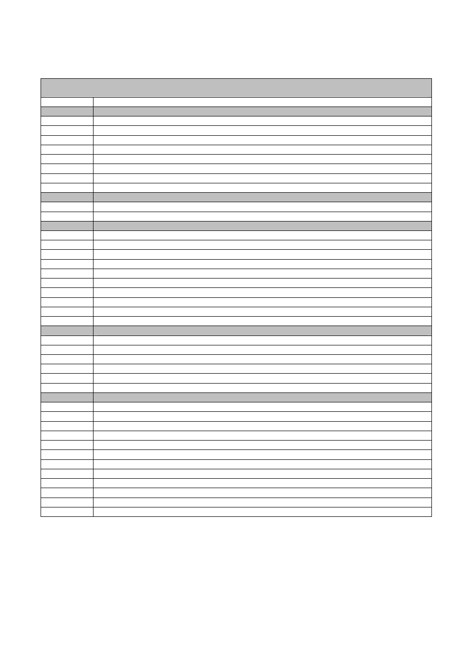
2.2.1 I/O configuration with 3-speed fans
c-Pro MICRO CAN with 2 A/O V+V (code CPU1S0C2V)
c-Pro EXP MICRO CAN with 2 A/O V+V (code CPUES0C2V)
I/O
Description
Analogue inputs
AI 1
Anti-freeze Temperature Probe (Recovery heat exchanger By-Pass) - NTC
AI 2
Supply Air Temperature Probe - NTC
AI 3
Return Air Temperature Probe - NTC
AI 4
CO
2
probe (0-5 V) (Optional)
AI 5
Outdoor Air Temperature Probe - NTC
AI 6
Not used
AI 7
Not used
AI 8
Not used
Serial ports
TTL (485)
TTL with external interface EVIF becomes RS485 Modbus RTU
CAN bus
To the EXP micro and/or Vgraph
Digital inputs
DI 1
Presence sensor
DI 2
Start – Stop (remote)
DI 3
Supply fan thermal overload (protection)
DI 4
Return fan thermal overload (protection)
DI 5
BY-Pass presence ( anti-freeze recovery heat exchanger)
DI 6
Differential pressure switch
DI 7
Hot water coil anti-freeze thermostat
DI 8
Electric heaters thermal overload
DI 9
Outside air damper limit switch (full open)
DI 10
Outside air damper limit switch (full closed)
Analogue outputs
AO 1
Not used
AO 2
Hot water coil modulating valve control (0-10 V)
AO 3*
Recovery heat exchanger BY-PASS damper control (0-10 V)
AO 4
Not used
AO 5
Not used
AO 6
Not used
Digital Outputs (Relay)
DO 1
Return fan first speed
DO 2
Return fan second speed
DO 3
Return fan third speed
DO 4
Supply fan first speed
DO 5
Supply fan second speed
DO 6
Supply fan third speed
DO 7*
Recovery heat exchanger BY-PASS damper
DO 8
Outside air damper
DO 9
Electric heaters step 1
DO 10
Electric heaters step 2
DO 11
Electric heaters step 3
DO 12
Generic alarm (can be configured)
(*) The control of the Recovery heat exchanger By-Pass damper can be digital or analogue, by setting the relevant
PG03 parameter.
RTC system clock - Real Time Clock: present on the user interface VGraph