EVCO c-pro micro SAVE User Manual
Page 32
C-PRO MICRO SAVE APPLICATION MANUAL
Page 32
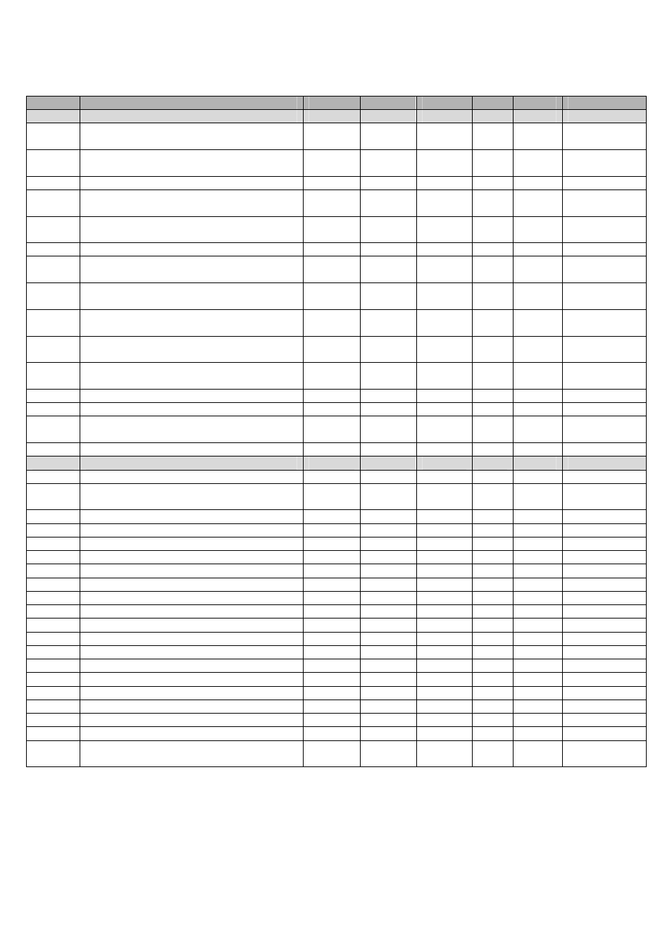
Code
Parameter description
Default
Min
Max
UM
Menu
Notes
ALARM PARAMETERS
PA03
Enabling of outlet/return fans thermal switch
alarm
Active
(1)
Not-
active (0)
Active
(1)
-
CO-S
PA05
Enabling of differential pressure switch alarm
Active
(1)
Not-
active (0)
Active
(1)
Sec
CO-S
PA06
Delay of differential pressure switch alarm
10
0
999
Sec
CO-S
PA08
Signals differential pressure switch alarm on
alarm relay
Yes (1)
No (0)
Yes (1)
Sec
CO-S
Only if
PG02=0
PA09
Anti-freeze alarm active on hot water coil
Not-
active (0)
Not-
active (0)
Active
(1)
Sec
CO-S
PA10
Anti-freeze alarm delay on hot water coil
10
0
999
Sec
CO-S
PA12
Activates the heaters thermal overload alarm
Active
(1)
Not-
active (0)
Active
(1)
Sec
CO-S
Only if
PG02=1
PA13
Signals heaters thermal switch alarm on alarm
relay
Yes (1)
No (0)
Yes (1)
CO-S
Only if
PG02=1
PA16
Enable supply high temperature alarm from
temperature probe
Active
(1)
Not-
active (0)
Active
(1)
CO-S
PA17
Supply high temperature alarm setpoint
85.0
PH01
PH02
°C
°F
CO-S
PA19
Supply high/low temperature alarms
differential
3.0
0.0
0.0
20.0
36.0
°C
°F
CO-S
PA20
High/low temperature alarms delay
10
0
999
Sec
CO-S
PA22
Expansion alarm delay
5
0
999
Sec
CO-S
PA24
RTC alarm enabling
Active
(1)
Not-
active (0)
Active
(1)
-
CO-S
PA26
Probes alarms signals delay
10
0
240
Sec
CO-S
VARIOUS PARAMETERS
PH11
Board Modbus address
1
1
247
-
CO-V
PH12
Communication Baud Rate for the board
(0=1200, 1=2400, 2=4800, 3=9600, 4=19200)
3
0
4
-
CO-V
PH13
ModBus Parity (0=none, 1=Odd, 2=Even)
2
0
2
-
CO-V
PH14
Stop Bit ModBus (0=1bit, 1=2bit)
0
0
1
-
CO-V
PH40
Enable outlet temperature probe
Yes (1)
No (0)
Yes (1)
-
CO-V
PH41
Enable return temperature probe
Yes (1)
No (0)
Yes (1)
-
CO-V
PH42
Enable CO
2
probe (0-5V)
No (0)
No (0)
Yes (1)
-
CO-V
PH43
Enable outside air temperature probe
Yes (1)
No (0)
Yes (1)
-
CO-V
PH51
Logic of the digital input DI1
N.O. (0)
N.O. (0)
N.C. (1)
-
CO-V
PH52
Logic of the digital input DI2
N.O. (0)
N.O. (0)
N.C. (1)
-
CO-V
PH53
Logic of the digital input DI3
N.C. (1)
N.O. (0)
N.C. (1)
-
CO-V
PH54
Logic of the digital input DI4
N.C. (1)
N.O. (0)
N.C. (1)
-
CO-V
PH55
Logic of the digital input DI5
N.O. (0)
N.O. (0)
N.C. (1)
-
CO-V
PH56
Logic of the digital input DI6
N.C. (1)
N.O. (0)
N.C. (1)
-
CO-V
PH57
Logic of the digital input DI7
N.O. (0)
N.O. (0)
N.C. (1)
-
CO-V
PH58
Logic of the digital input DI8
N.C. (1)
N.O. (0)
N.C. (1)
-
CO-V
PH59
Logic of the digital input DI9
N.O. (0)
N.O. (0)
N.C. (1)
-
CO-V
PH60
Logic of the alarm relay DO10
N.O. (0)
N.O. (0)
N.C. (1)
-
CO-V
PH61
Logic of the alarm relay DO12
N.O. (0)
N.O. (0)
N.C. (1)
-
CO-V
PH80
CAN communication Baud Rate
(20K, 50K, 125K, 500K)
1
1
4
-
CO-V
Notes:The outside air return probes activation parameters, respectively PH41 and PH43 are conditioned by the state of
the digital input that indicates the presence of the By-Pass damper (DI5). If the input confirms the presence of the By-
Pass, the two parameters are active, otherwise they are deactivated. Any changes to the parameters are allowed, but any
change in state of the digital input DI5 implies changes of the two parameters.
Once the machine parameters have been configured and at every modification of the configuration parameters, it is
advised to remove and re-apply the power supply to the board to allow the control to configure itself correctly.