2applications, 1 compact solution – EVCO c-pro micro SAVE User Manual
Page 5
C-PRO MICRO SAVE APPLICATION MANUAL
Page 5
2
Applications
2.1
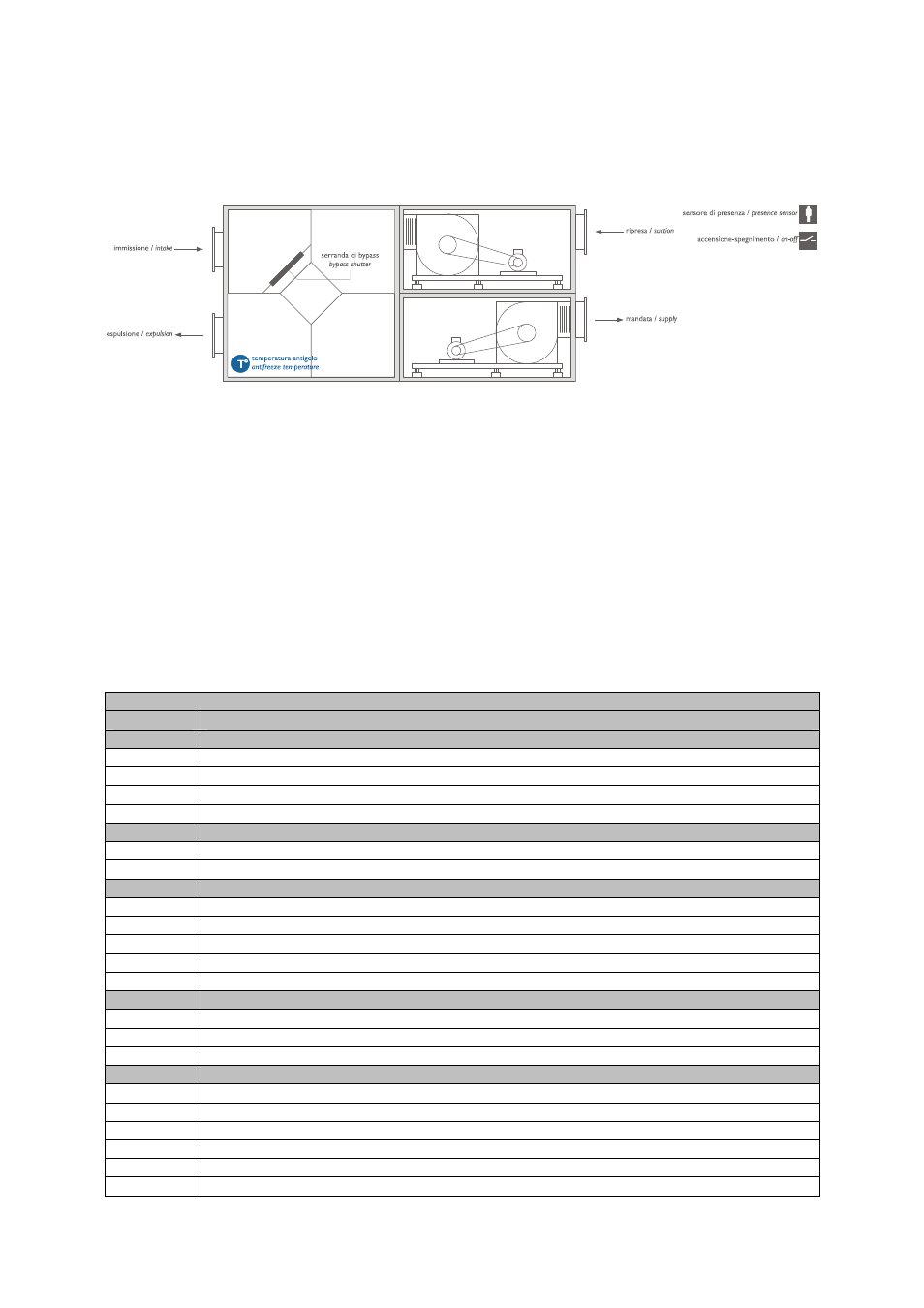
COMPACT solution
The picture above shows a principle layout. It is intended for indicating the presence of the components, not their position, in
the AHU controlled by the EVCO device. It is also NOT intended for indicating the real layout of the AHU.
The unit has the following main features:
•
N° 2 Fans with 3 speeds or with 1 speed + speed variator
•
N° 1 Heat exchanger/Cross flow recovery heat exchanger
•
N° 1 Recovery heat exchanger By-pass damper (optional)
•
N° 1 Recovery heat exchanger anti-freeze temperature probe
•
N° 1 Presence sensor (installed in the room)
•
N° 1 Start – Stop (remote)
Note: The compact solution is by default configured for piloting 3-speed fans (PG10 = DO)
2.1.1 I/O configuration with 3-speed fans
c-Pro MICRO CAN with 2 AO (V+V) (code CPU1S0C2)
I/O
Description
Analogue inputs
AI 1
Anti-freeze Temperature Probe (Recovery heat exchanger By-Pass) NTC
AI 2
Not used
AI 3
Not used
AI 4
Not used
Serial ports
TTL (485)
(TTL with external interface EVIF becomes RS485 Modbus RTU)
CAN bus
To the EXP micro and/or Vgraph
Digital inputs
DI 1
Presence sensor
DI 2
Start – Stop (remote)
DI 3
Supply fan thermal overload
DI 4
Return fan thermal overload
DI 5
By-pass damper presence (anti-freeze recovery heat exchanger)
Analogue outputs
AO 1
Not used
AO 2
Not used
AO 3
Recovery heat exchanger BY-PASS damper control (0-10 V)
Digital Outputs (Relay)
DO 1
Return fan speed 1
DO 2
Return fan speed 2
DO 3
Return fan speed 3
DO 4
Supply fan speed 1
DO 5
Supply fan speed 2
DO 6
Supply fan speed 3
RTC system clock - Real Time Clock: present on user interface VGraph