4 connection lay out for c-pro exp micro can – EVCO c-pro micro SAVE User Manual
Page 15
C-PRO MICRO SAVE APPLICATION MANUAL
Page 15
2.4
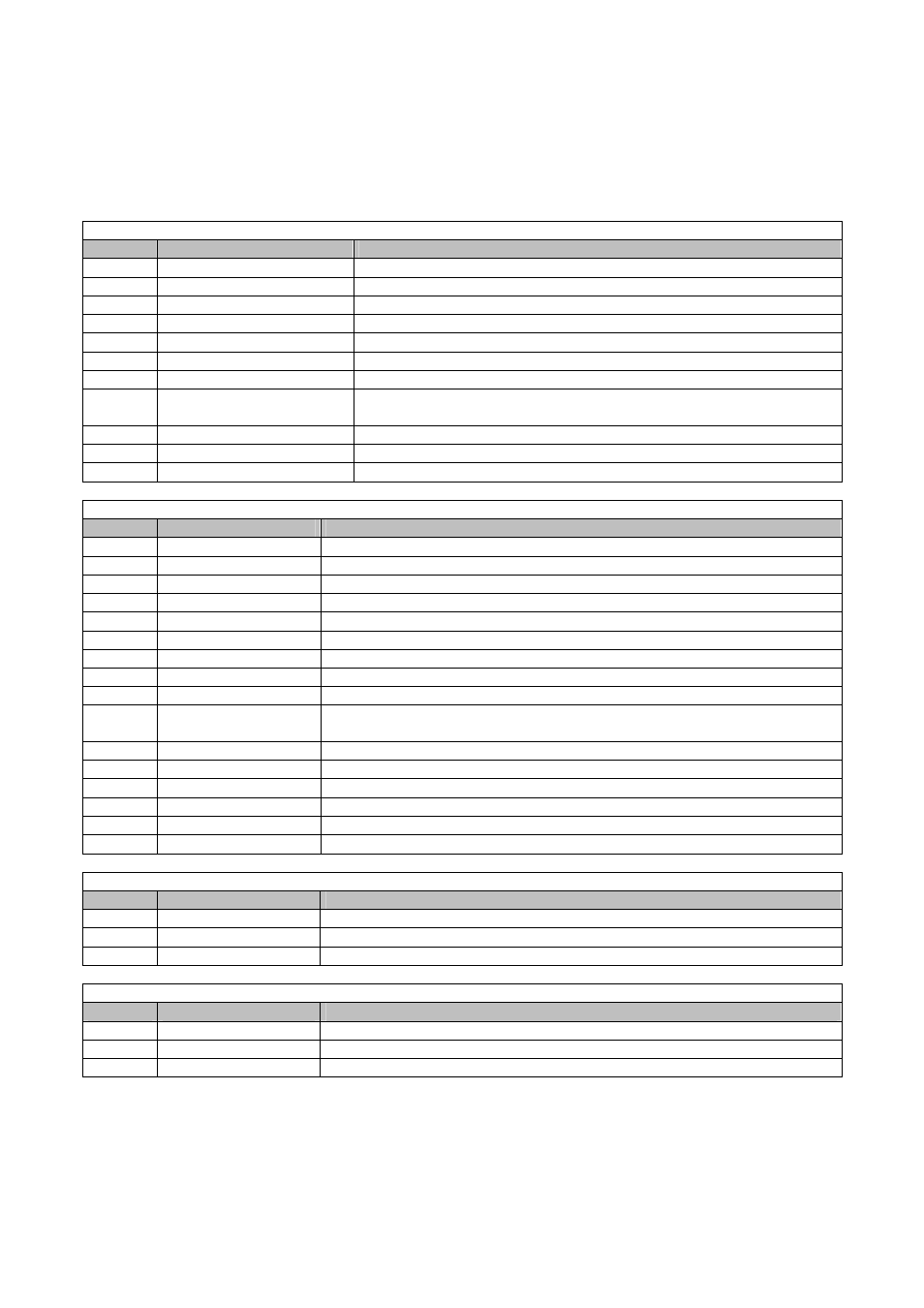
Connection lay out for C-PRO EXP MICRO CAN
Below find the connection lay out of the expansion with tables relevant to the meaning of the inputs
and outputs.
Connector 1: Connection for the relay outputs
Conn.
Code
Description
C1-1
DO1
Relay n.1 normally open contact
C1-2
COMMON DO1
Common relay n.1
C1-3
DO2
Relay n.2 normally open contact
C1-4
COMMON DO2
Common relay n.2
C1-5
DO3
Relay n.3 normally open contact
C1-6
COMMON DO3
Common relay n.3
C1-7
DO4
Relay n.4 normally open contact
C1-8
COMMON DO4,
DO5
Common relay n.4, 5
C1-9
DO5
Relay n.5 normally open contact
C1-11
DO6
Relay n.6 normally open contact
C1-12
COMMON DO6
Common relay n.6
Connector 2: Connector for low voltage signals
Conn.
Code
Description
C2-1
12VAC
Power supply (12VAC/DC)
C2-2
Not connected
Not connected
C2-3
GND
Common analogue and digital inputs
C2-4
GND
Common analogue and digital inputs
C2-5
AI4
Analogue input n.4 (for NTC 0/4-20 mA or 0-5V transducers)
C2-6
AI3
Analogue input n.3 (for NTC 0/4-20 mA or 0-5V transducers)
C2-7
AI2
Analogue input n.2 (for NTC probes)
C2-8
AI1
Analogue input n.1 (for NTC probes)
C2-9
12VAC
Power supply (12VAC/DC)
C2-10
12VDC
0/4-20 mA transducers and phase cut module power supply
(max. 50 mA, not protected against short circuit)
C2-11
AO1
Jog output for phase cut module
C2-12
DI5
Digital input n.5
C2-13
DI4
Digital input n.4
C2-14
DI3
Digital input n.3
C2-15
DI2
Digital input n.2
C2-16
DI1
Digital input n.1
Connector 3: Connector for the controller (IntraBus)
Conn.
Code
Description
C3-1
12VDC
Power supply
C3-2
GND
Common
C3-3
DATA
Serial live
Connector 3: Connector for the controller (CAN)
Conn.
Code
Description
C3-1
CAN +
Connector for the connection of the CAN + serial port
C3-2
GND
Mass reference connector
C3-3
CAN -
Connector for the connection of the CAN - serial port