EVCO c-pro micro SAVE User Manual
Page 27
C-PRO MICRO SAVE APPLICATION MANUAL
Page 27
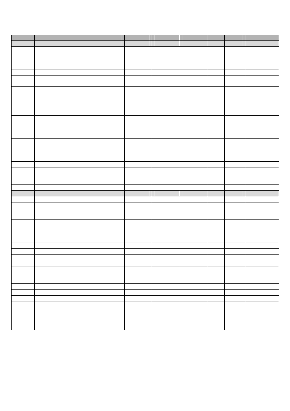
Code
Parameter description
Default
Min
Max
UM
Menu
Notes
ALARM PARAMETERS
PA03
Enabling of supply/return fans thermal
overload alarm
Active (1)
Not-active
(0)
Active (1)
-
CO-S
PA05
Enabling of differential pressure switch
alarm
Not-active
(0)
Not-active
(0)
Active (1)
Sec
CO-S
PA06
Delay of differential pressure switch alarm
10
0
999
Sec
CO-S
PA08
Signals differential pressure switch alarm
on alarm relay
No (0)
No (0)
Yes (1)
Sec
CO-S
Only if
PG02=0
PA09
Anti-freeze alarm active on hot water coil
Not-active
(0)
Not-active
(0)
Active (1)
Sec
CO-S
PA10
Anti-freeze alarm delay on hot water coil
10
0
999
Sec
CO-S
PA12
Activates the heaters thermal switch alarm
Not-active
(0)
Not-active
(0)
Active (1)
Sec
CO-S
Only if
PG02=1
PA13
Signals heaters thermal overload alarm on
alarm relay
No (1)
No (0)
Yes (1)
CO-S
Only if
PG02=1
PA16
Enable supply high temperature alarm
from temperature probe
Not-active
(0)
Not-active
(0)
Active (1)
CO-S
PA17
Supply high temperature alarm setpoint
85.0
PH01
PH02
°C
°F
CO-S
PA19
Supply high/low temperature alarms
differential
3.0
0.0
0.0
20.0
36.0
°C
°F
CO-S
PA20
High/low temperature alarms delay
10
0
999
Sec
CO-S
PA22
Expansion alarm delay
5
0
999
Sec
CO-S
PA24
RTC alarm enabling
Active (1)
Not-active
(0)
Active (1)
-
CO-S
PA26
Probes alarms signals delay
10
0
240
Sec
CO-S
VARIOUS PARAMETERS
PH11
Board Modbus address
1
1
247
-
CO-V
PH12
Communication Baud Rate for the board
(0=1200, 1=2400, 2=4800, 3=9600,
4=19200)
3
0
4
-
CO-V
PH13
ModBus Parity (0=none, 1=Odd, 2=Even)
2
0
2
-
CO-V
PH14
Stop Bit ModBus (0=1bit, 1=2bit)
0
0
1
-
CO-V
PH40
Enable supply temperature probe
No (01)
No (0)
Yes (1)
-
CO-V
PH41
Enable return temperature probe
No (0)
No (0)
Yes (1)
-
CO-V
PH42
Enable CO
2
probe (0-5V)
No (0)
No (0)
Yes (1)
-
CO-V
PH43
Enable outside air temperature probe
No (0)
No (0)
Yes (1)
-
CO-V
PH51
Logic of the digital input DI1
N.O. (0)
N.O. (0)
N.C. (1)
-
CO-V
PH52
Logic of the digital input DI2
N.O. (0)
N.O. (0)
N.C. (1)
-
CO-V
PH53
Logic of the digital input DI3
N.C. (1)
N.O. (0)
N.C. (1)
-
CO-V
PH54
Logic of the digital input DI4
N.C. (1)
N.O. (0)
N.C. (1)
-
CO-V
PH55
Logic of the digital input DI5
N.O. (0)
N.O. (0)
N.C. (1)
-
CO-V
PH56
Logic of the digital input DI6
N.C. (1)
N.O. (0)
N.C. (1)
-
CO-V
PH57
Logic of the digital input DI7
N.O. (0)
N.O. (0)
N.C. (1)
-
CO-V
PH58
Logic of the digital input DI8
N.C. (1)
N.O. (0)
N.C. (1)
-
CO-V
PH59
Logic of the digital input DI9
N.O. (0)
N.O. (0)
N.C. (1)
-
CO-V
PH60
Logic of the alarm relay DO10
N.O. (0)
N.O. (0)
N.C. (1)
-
CO-V
PH61
Logic of the alarm relay DO12
N.O. (0)
N.O. (0)
N.C. (1)
-
CO-V
PH80
CAN communication Baud Rate
(20K, 50K, 125K, 500K)
1
1
4
-
CO-V
Note: Once the unit parameters have been configured and at each modification of the configuration parameters it is
recommended to switch OFF / switch ON the power supply to the board to make sure the configuration has been
correctly updated.