3 connection lay out for c-pro micro can – EVCO c-pro micro SAVE User Manual
Page 13
C-PRO MICRO SAVE APPLICATION MANUAL
Page 13
2.3
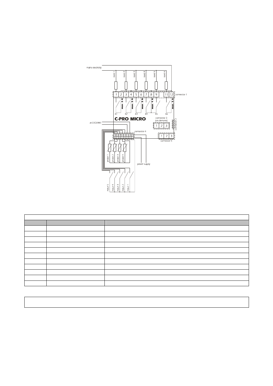
Connection lay out for C-PRO MICRO CAN
Below find the connection lay out of the C-PRO MICRO controller with tables relevant to the
meaning of the inputs and outputs.
C-PRO MICRO connections
Connector 1: Connection for the relay outputs
Conn.
Code
Description
C1-1
DO1
Relay n.1 normally open contact
C1-2
COMMON DO1
Common relay n.1
C1-3
DO2
Relay n.2 normally open contact
C1-4
COMMON DO2
Common relay n.2
C1-5
DO3
Relay n.3 normally open contact
C1-6
COMMON DO3
Common relay n.3
C1-7
DO4
Relay n.4 normally open contact
C1-8
COMMON DO4, DO5
Common relay n.4,5
C1-9
DO5
Relay n.5 normally open contact
C1-11
DO6
Relay n.6 normally open contact
C1-12
COMMON DO6
Common relay n.6
Connector 2: Connection for the upload/download parameters and/or output pen for RS485 module and/or controller
flash download module
- EV3B22N7 (2 pages)
- EV3B23N7 (2 pages)
- EV3B31N7 (2 pages)
- EV3X21N7 (2 pages)
- EVK203N7 (2 pages)
- EVK204N9 (5 pages)
- EVK214N9 (6 pages)
- EVX201N7 (8 pages)
- EVX225N7 (6 pages)
- EVXS214N9 (8 pages)
- EVXV201N7 (9 pages)
- EVR202N7 (10 pages)
- EVRS204N9 (8 pages)
- EVRS225N9 (10 pages)
- TM102A (2 pages)
- EVK404N9 (8 pages)
- EPD4BF3 (2 pages)
- EPD4BF3 (70 pages)
- EV6223P7 (2 pages)
- EVB1226N9XXC (92 pages)
- EVB1214N9 (88 pages)
- EVRSF204N9VRB (8 pages)
- EVF204N9 (8 pages)
- EVF205N9 (8 pages)
- EVF214N9 (8 pages)
- EVF215N9 (8 pages)
- EK820AP7 (4 pages)
- EK825AP7 (14 pages)
- EVCSR818P9EF (94 pages)
- EVF815P9 (2 pages)
- EVF815P9 (60 pages)
- EVF818P9 (2 pages)
- EVF818P9 (76 pages)
- EVX802P7 Installer manual (2 pages)
- EVX802P7 Installer manual (66 pages)
- EVXS815P9 Installer manual (2 pages)
- EVXS815P9 Installer manual (60 pages)
- EVXV802P7 Installer manual (2 pages)
- EVXV802P7 Installer manual (66 pages)
- EVK802P7 (2 pages)
- EVFTFT818P7U (2 pages)
- EVFTFT818P7U Installer manual (94 pages)
- EV7601J6 (2 pages)
- EV9303J9 (2 pages)
- EV9313J9 (2 pages)