4 list of configuration parameters – EVCO EVFTFT818P7U Installer manual User Manual
Page 58
EVCO S.p.A.
EVFTFT818 | Installer manual ver. 2.1 | Code 144FTFT818E214
page 58 of 94
11.4
List of configuration parameters
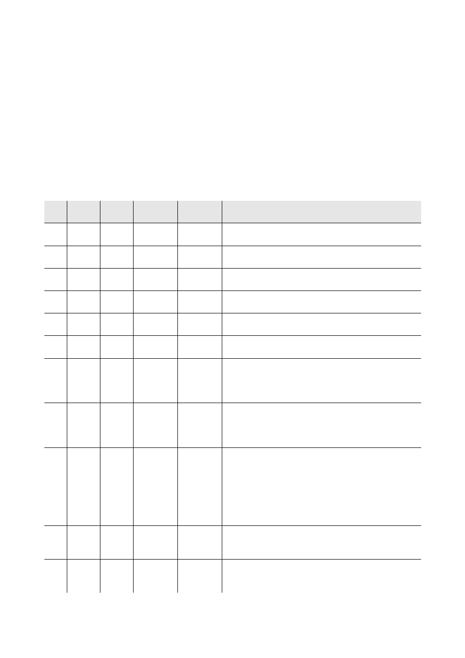
The following table illustrates the meaning of the configuration parameters.
The management of some inputs and outputs is subject to the value set with some parameters, as follows:
-
management of the needle probe is only available if parameter P3 is set at values different to 0
-
management of the evaporator probe is only available if the parameter P4 is set at 1
-
management of the condenser probe is only available if the parameter P5 is set at 1
-
management of the cabinet light is only available if the parameter u11 is set at 0
-
management of the UV light is only available if parameter u11 is set at 1.
-
management of the pump down valve is only available if parameter u1 is set at 0
-
management of the alarm output is only available if parameter u1 is set at 1.
The evaporator fan control signal can be analogue (parameter F0 set at 3) or digital (parameter F0 set at values
different to 3).
Par.
Min.
Max.
Unit
Default
Analogue inputs
CA1
-25
25
°C/°F (1)
0
cabinet probe offset
CA2
-25
25
°C/°F (1)
0
needle probe offset 1
CA3
-25
25
°C/°F (1)
0
evaporator probe offset
CA4
-25
25
°C/°F (1)
0
condenser probe offset
CA5
-25
25
°C/°F (1)
0
needle probe offset 2
CA6
-25
25
°C/°F (1)
0
needle probe offset 3
P0
0
1
- - - -
0
probe type
0 = PTC
1 = NTC
P2
0
1
- - - -
0
temperature unit of measurement (2)
0 = °C
1 = °F
P3
0
3
- - - -
1
number of needle probe sensors
0 = needle probe not available
1 = 1 (needle probe 1)
2 = 2 (needle probe 1 and needle probe 2)
3 = 3 (needle probe 1, needle probe 2 and needle probe
3)
P4
0
1
- - - -
1
enabling the evaporator probe
1 = yes
P5
0
1
- - - -
1
enabling the condenser probe
1 = yes