2 igniter, 2 igniter 72 – AERCO Innovation (G-13-1854 and above) User Manual
Page 72
Innovation Water Heaters Installation, Operation & Maintenance Manual
CHAPTER 6 – MAINTENANCE
Page 72 of
196
AERCO International, Inc. • 100 Oritani Dr. • Blauvelt, NY 10913
OMM-0078_0J
PRI: 11/22/2013
Phone: 800-526-0288
GF-128
6.2 IGNITER
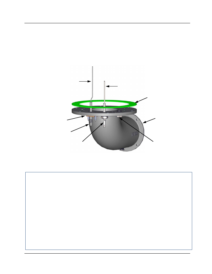
The igniter is located on the flange of the blower-side intake manifold located at the bottom of the
unit’s heat exchanger. The igniter part number (66023) is the same for Natural Gas and Propane
units. Figure 6-1 shows the blower-side intake manifold removed from the heater and indicates
the locations of the igniter, flame detector and other related components.
The igniter may be hot, therefore, care should be exercised to avoid burns. It is easier to remove
the igniter from the unit after the unit has cooled to room temperature.
Figure 6-1. Blower-Side intake Manifold With Igniter & Flame Detector
To inspect/replace the Igniter:
Igniter Inspection/Replacement
1. Set the ON/OFF switch on the control panel, to the OFF position. Disconnect AC power
from the unit.
2. Remove the side and rear panels from the unit.
3. Disconnect the ignition cable and ground wire from the Igniter.
4. Next, loosen and remove the igniter from the intake manifold flange using a 1" open-end
wrench.
5. Check the igniter for evidence of erosion or carbon build-up. If there is evidence of
substantial erosion or carbon build-up, the igniter should be replaced. If carbon build-up is
present, clean the component using fine emery cloth. Repeated carbon build-up is an
indication that the combustion settings of the unit should be checked. Refer to Chapter 4 for
combustion calibration procedures.
6. Prior to reinstalling the igniter, a high temperature, conductive, anti-seize compound must
be applied to the threads.
FLAME
DETECTOR
BLOWER SIDE
INTAKE
MANIFOLD
IGNITOR
FLAME
DETECTOR
FLAME DETECTOR
GASKET
BURNER FLANGE
GASKET
OBSERVATION
PORT
IGNITOR