2 installing gas supply manometer, 3 accessing the analyzer probe port – AERCO Innovation (G-13-1854 and above) User Manual
Page 50
Innovation Water Heaters Installation, Operation & Maintenance Manual
CHAPTER 4 – INITIAL START-UP
Page 50 of
196
AERCO International, Inc. • 100 Oritani Dr. • Blauvelt, NY 10913
OMM-0078_0J
PRI: 11/22/2013
Phone: 800-526-0288
GF-128
• Digital Combustion Analyzer: Oxygen accuracy to ± 0.4%; Carbon Monoxide (CO) and
Nitrogen Oxide (NOx) resolution to 1PPM.
• 16 inch W.C. manometer or equivalent gauge and plastic tubing.
• Multimeter (Capable of measuring 0 – 10 µA)
• 1/8 inch NPT-to-barbed fittings for use with gas supply manometer or gauge.
• Small and large flat blade screwdrivers.
• Tube of silicone adhesive
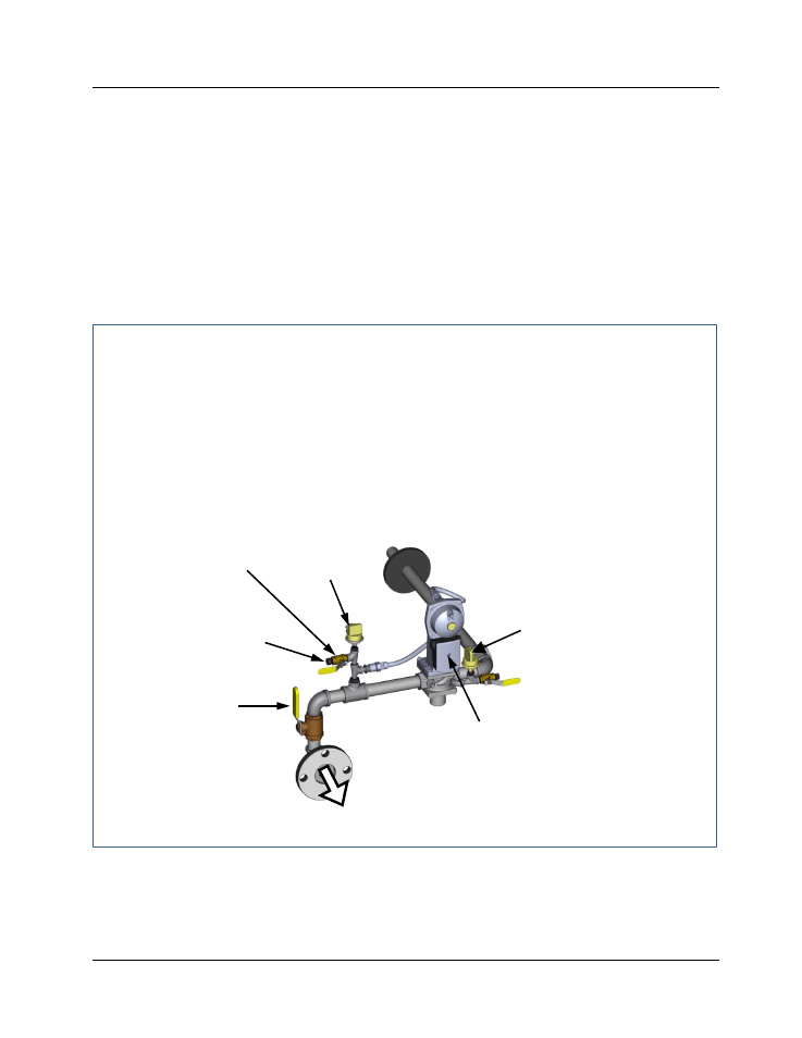
4.2.2 Installing Gas Supply Manometer
The gas supply manometer is installed in the gas train as follows:
Installing Gas Supply Manometer
1. Close the main manual gas supply shut-off valve upstream of the unit.
2. Remove the front door and left side panels from the heater to access the gas train
components.
3. Remove the 1/4 inch NPT pipe plug from the leak detection ball valve on the downstream
side of the Safety Shut Off Valve (SSOV) as shown in Figure 4-1.
4. Install a NPT-to-barbed fitting into the tapped plug port.
5. Attach one end of the plastic tubing to the barbed fitting and the other end to the 16 inch
W.C. manometer.
Figure 4-1. 1/4 Inch Gas Plug Location (INN1060 Gas Train Shown)
4.2.3 Accessing the Analyzer Probe Port
The unit contains a 1/8” NPT port at the rear of the exhaust manifold. This port is located above
the condensate drain connection as shown in Figure 4-2. Prepare the port for the combustion
analyzer probe as follows:
MANUAL
SHUTOFF
VALVE
SSOV
1/4" NPT PLUG
(Install manometer here)
LEAK
DETECTION
BALL VALVE
TO AIR/FUEL
VALVE
LOW GAS
PRESSURE SWITCH
HIGH GAS
PRESSURE
SWITCH