AERCO Innovation (G-13-1854 and above) User Manual
Page 53
Innovation Water Heaters Installation, Operation & Maintenance Manual
CHAPTER 4 – INITIAL START-UP
OMM-0078_0J
AERCO International, Inc. • 100 Oritani Dr. • Blauvelt, NY 10913
Page 53 of
196
GF-128
Phone: 800-526-0288
PRI: 11/22/2013
Natural Gas Combustion Calibration
1. Open the water supply and return valves to the unit and ensure that the system pumps are
running.
2. Open the natural gas supply valve(s) to the unit.
3. Set the control panel ON/OFF switch to the OFF position.
4. Turn on external AC power to the unit. The display will show LOSS OF POWER and the
time and date.
5. Set the unit to the Manual Mode by pressing the AUTO/MAN key. A flashing Manual Valve
Position message will be displayed with the present position in %. Also, the MANUAL LED
will light.
6. Adjust the air/fuel valve position to 0% by pressing the
▼ arrow key.
7. Ensure that the leak detection ball valve downstream of the SSOV is open.
8. Set the ON/OFF switch to the ON position.
9.
Change the valve position to 29% using the ▲ arrow key. The unit should begin its start
sequence and fire.
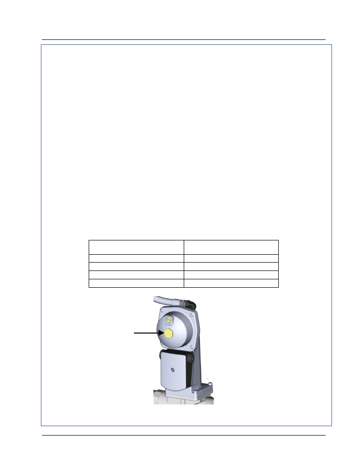
10. Next, verify that the gas pressure downstream of the SSOV is within the appropriate range
shown below for the Innovation Model being tested. If gas pressure adjustment is required,
remove the brass hex nut on the SSOV actuator to access the gas pressure adjustment
screw (Figure 4-4). Make gas pressure adjustments using a flat-tip screwdriver to obtain a
gas pressure reading within the required range for the INN model being tested.
INNOVATION MODEL
GAS PRESSURE RANGE
DOWNSTREAM OF SSOV
INN 1350
3.0” – 3.2” W.C.
INN1060
2.6” – 2.8” W.C.
INN800
1.5” – 1.7” W.C.
INN600
0.9” – 1.1” W.C.
Figure 4-4. Gas Pressure Adjustment Screw Location
BRASS HEX
HEAD CAP
(Remove to
access gas
pressure
adjustment