3 control and power wiring – AERCO Innovation (G-13-1854 and above) User Manual
Page 113
Innovation Water Heaters Installation, Operation & Maintenance Manual
CHAPTER 9 – WATER HEATER MANAGEMENT
OMM-0078_0J
AERCO International, Inc. • 100 Oritani Dr. • Blauvelt, NY 10913
Page 113 of
196
GF-128
Phone: 800-526-0288
PRI: 11/22/2013
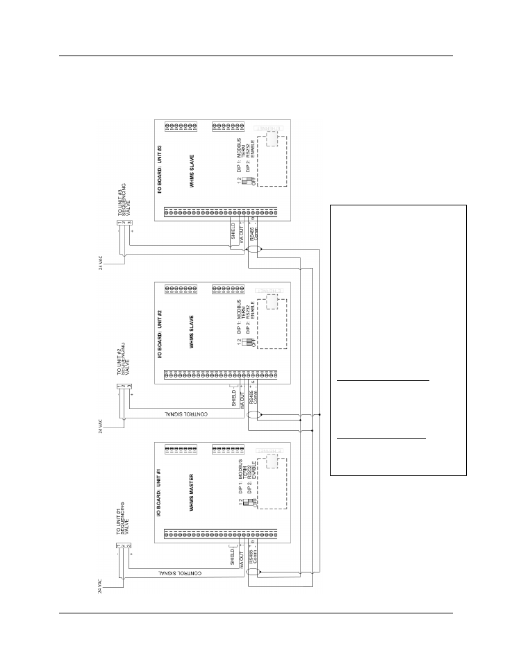
9.5.3 Control and Power Wiring
Control and power wiring connections to the sequencing valves associated with each C-More
WHM unit is accomplished by simply ensuring that the 3-pin Molex connectors on the units are
connected to the corresponding connectors on the valves.
Figure 9-4 WHMS Network Wiring Diagram
NOTES:
1. Wiring to be shielded twisted-
pair cable (Belden 9841 or
equivalent).
2. Activate DIP 1 (Modbus
TERM) on the first and last units
in the daisy chain.
3. Tie incoming/outgoing shields
together and terminate at the
shield terminal of the LAST
WHMS slave in the chain.
4. On the CPU board inside the
C-More Control Panel of the
FIRST unit on the chain, turn the
DIP switch labeled TERM to the
“ON” position.
5. On the CPU board inside the
C-More Control Panel of the
LAST unit on the chain, turn the
DIP switches labeled BIAS1,
TERM and BIAS2 to the “ON”
position.