7 system recirculation loop – AERCO Innovation (G-13-1854 and above) User Manual
Page 22
Innovation Water Heaters Installation, Operation & Maintenance Manual
CHAPTER 2 – INSTALLATION
Page 22 of
196
AERCO International, Inc. • 100 Oritani Dr. • Blauvelt, NY 10913
OMM-0078_0J
PRI: 11/22/2013
Phone: 800-526-0288
GF-128
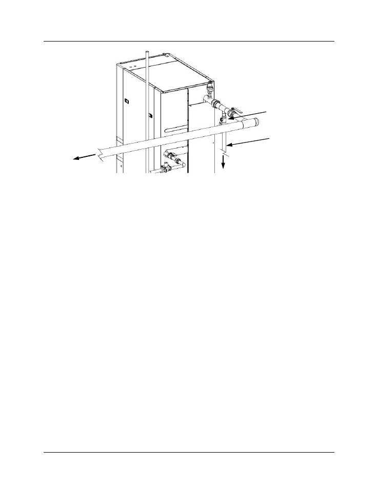
Figure 2-4. Test Hose Bib Location
2.7 SYSTEM RECIRCULATION LOOP
The System Recirculation Loop Assembly is located inside the unit enclosure at the rear of the
unit. In order to access this assembly, the right rear middle panel must be removed. Refer to
Figure 2-5. This assembly contains a recirculator pump which connects between the upper hot
water outlet and lower cold water inlet of the unit’s heat exchanger. The purpose of this loop is
to provide feed-forward (FFWD) temperature control by mixing a portion of the hot water outlet
with the cold water inlet of the unit. Temperature sensors located in the hot water outlet and cold
water inlet provide temperature data to the C-More Control System. The Control System utilizes
this data to modulate the fire rate (Air/Fuel Valve position) to precisely maintain the hot water
outlet temperature at the selected setpoint temperature.
TO DRAIN
TEST
HOSE BIB
HOT
WATER
OUT
HOSE
CONNECTION