3 accessing the analyzer probe port – AERCO BMK 6000 Dual Fuel User Manual
Page 61
Benchmark 6000 DF Installation, Operation & Maintenance Manual
CHAPTER 4 – INITIAL START-UP
OMM-0096_0B
AERCO International, Inc. • 100 Oritani Dr. • Blauvelt, NY 10913
Page 61 of 219
GF-141
Ph.: 800-526-0288
03/21/2014
Install the 16” W.C. manometer(s) as described in the following steps:
Installing Gas Supply Manometer
1.
Turn off the main gas supply upstream of the unit.
2.
Remove the top and front panels from the boiler to access the gas train components.
3.
To monitor the gas pressure on the downstream side of the SSOV during Combustion
Calibration (section 4.4 and 4.5), remove the 1/4” NPT plug from downstream side of the
SSOV as shown in Figure 4-1.
4.
Install a NPT-to-barbed fitting into the tapped plug port.
5.
Attach one end of the plastic tubing to the barbed fitting and the other end to the 16” W.C.
manometer.
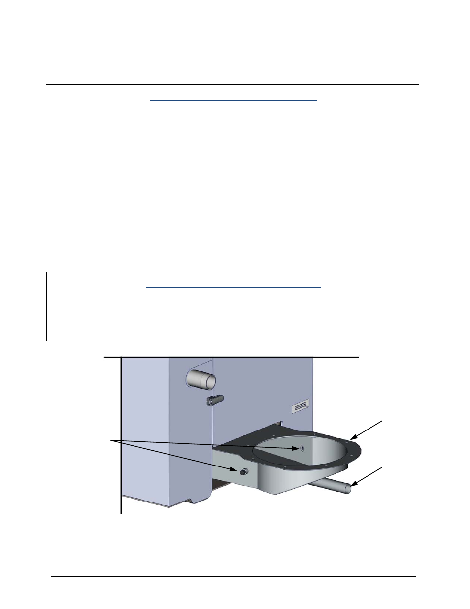
4.2.3 Accessing the Analyzer Probe Port
For easy access, the unit contains a total of two (2) 1/4” NPT ports, on the left and right sides of
the exhaust manifold (see Figure 4-2).
Prepare the selected port for the combustion analyzer probe as follows:
Accessing the Analyzer Probe Port
1.
Refer to Figure 4-2 and remove the 1/4” NPT plug from the desired location on the exhaust
manifold.
2.
If necessary, adjust the stop on the combustion analyzer probe. DO NOT install the probe
at this time.
Figure 4-2: Analyzer Probe Hole Location
ANALYZER PROBE
PORTS
(2) with 1/4” PLUG
PARTIAL REAR VIEW
CONDENSATE
DRAIN
EXHAUST
MANIFOLD