2 setting the unit – AERCO BMK 6000 Dual Fuel User Manual
Page 18
Benchmark 6000 DF Installation, Operation & Maintenance Manual
CHAPTER 2 – INSTALLATION
Page 18 of 219
AERCO International, Inc. • 100 Oritani Dr. • Blauvelt, NY 10913
OMM-0096_0B
03/21/2014
Ph.: 800-526-0288
GF-141
KEEP THE UNIT AREA CLEAR AND FREE FROM ALL COMBUSTIBLE
MATERIALS AND FLAMMABLE VAPORS OR LIQUIDS
.
FOR MASSACHUSSETTS ONLY
For Massachusetts installations, the unit must be installed by a plumber or
gas-fitter who is licensed within the Commonwealth of Massachusetts. In
addition, the installation must comply with all requirements specified in
Chapter 1 – Safety Precautions.
2.4.2 Setting the Unit
The unit must be installed on a concrete housekeeping pad, a minimum of 4 inches and a
maximum of 8 inches thick, to ensure proper condensate drainage (see NOTE below).
NOTE
When using the AERCO Condensate Neutralizer Tank for proper
condensate drainage, the Neutralizer Tank must be stored in a pit, OR the
boiler and AERCO Condensate Trap must be elevated higher than 4” above
the floor. Ensure that the condensate assembly is not positioned above the
housekeeping pad during installation so as not to interference with
condensate piping. See Condensate Tank Instructions TID-0074 for details.
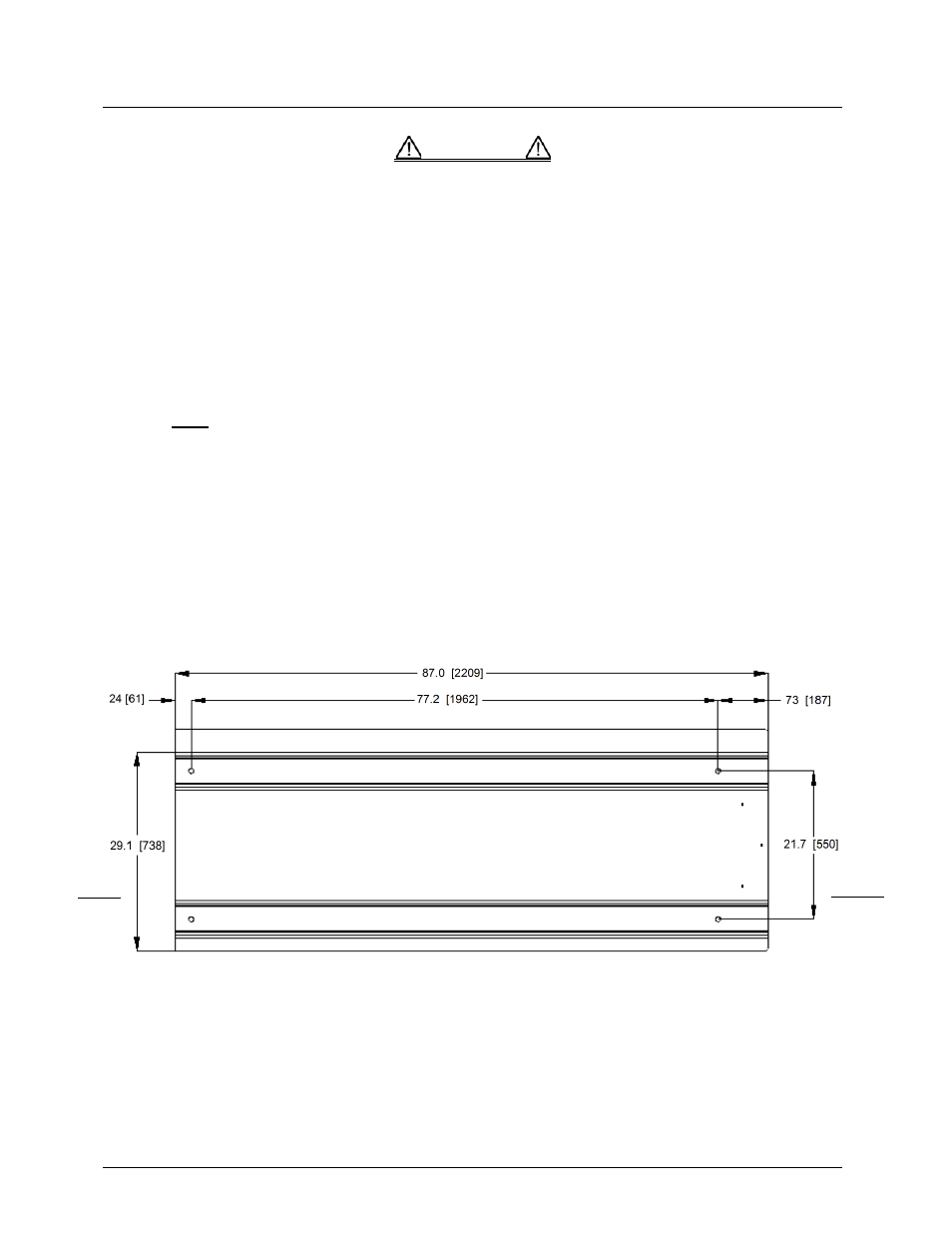
If anchoring the unit, refer to Figure 2-2b for anchor bolt locations.
• All holes are flush with the bottom surface of the frame.
• All dimensions shown are in inches [millimeters]
Figure 2-2b. Benchmark 6000 Anchor Bolt Locations
Two (2) lifting lugs are provided at the top of the primary heat exchanger as shown in Figure 2-3.
Cut the cardboard at marked locations to provide access to the lifting tabs.
WARNING
REAR
FRONT