2 pressure/temperature gauge installation – AERCO BMK 6000 Dual Fuel User Manual
Page 21
Benchmark 6000 DF Installation, Operation & Maintenance Manual
CHAPTER 2 – INSTALLATION
OMM-0096_0B
AERCO International, Inc. • 100 Oritani Dr. • Blauvelt, NY 10913
Page 21 of 219
GF-141
Ph.: 800-526-0288
03/21/2014
connections. Any excess should be wiped off to avoid getting any joint compound into the valve
body. Each relief valve must be piped to within 12 inches of the floor to prevent injury in the
event of a discharge. The discharge piping must be full size, without reduction. No valve or size
reductions are allowed in the discharge line. In multiple unit installations the discharge lines must
not be manifolded together. Each must be individually run to a suitable discharge location.
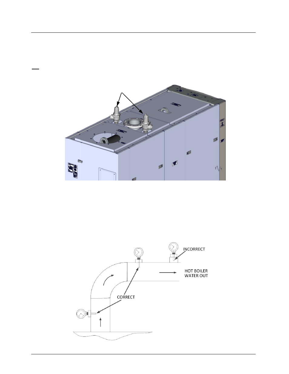
Figure 2-5A. Pressure Relief Valve Installation Locations
2.6.2 Pressure/Temperature Gauge Installation
A manual Pressure/Temperature Gauge is included in the loose parts kit for installation for
installation in the boiler outlet piping. It must be installed so that the sensing bulb is inserted into
the hot water outlet flow from the boiler. Refer to Figure 2-5B for sample installations.
Figure 2-5B. Pressure/Temperature Gauge Installation Location
PRESSURE RELIEF
VALVES