7 condensate drain & piping – AERCO BMK 6000 Dual Fuel User Manual
Page 22
Benchmark 6000 DF Installation, Operation & Maintenance Manual
CHAPTER 2 – INSTALLATION
Page 22 of 219
AERCO International, Inc. • 100 Oritani Dr. • Blauvelt, NY 10913
OMM-0096_0B
03/21/2014
Ph.: 800-526-0288
GF-141
2.7 CONDENSATE DRAIN & PIPING
The Benchmark boiler is designed to condense water vapor from the flue products. Therefore,
the installation must have provisions for suitable condensate drainage or collection.
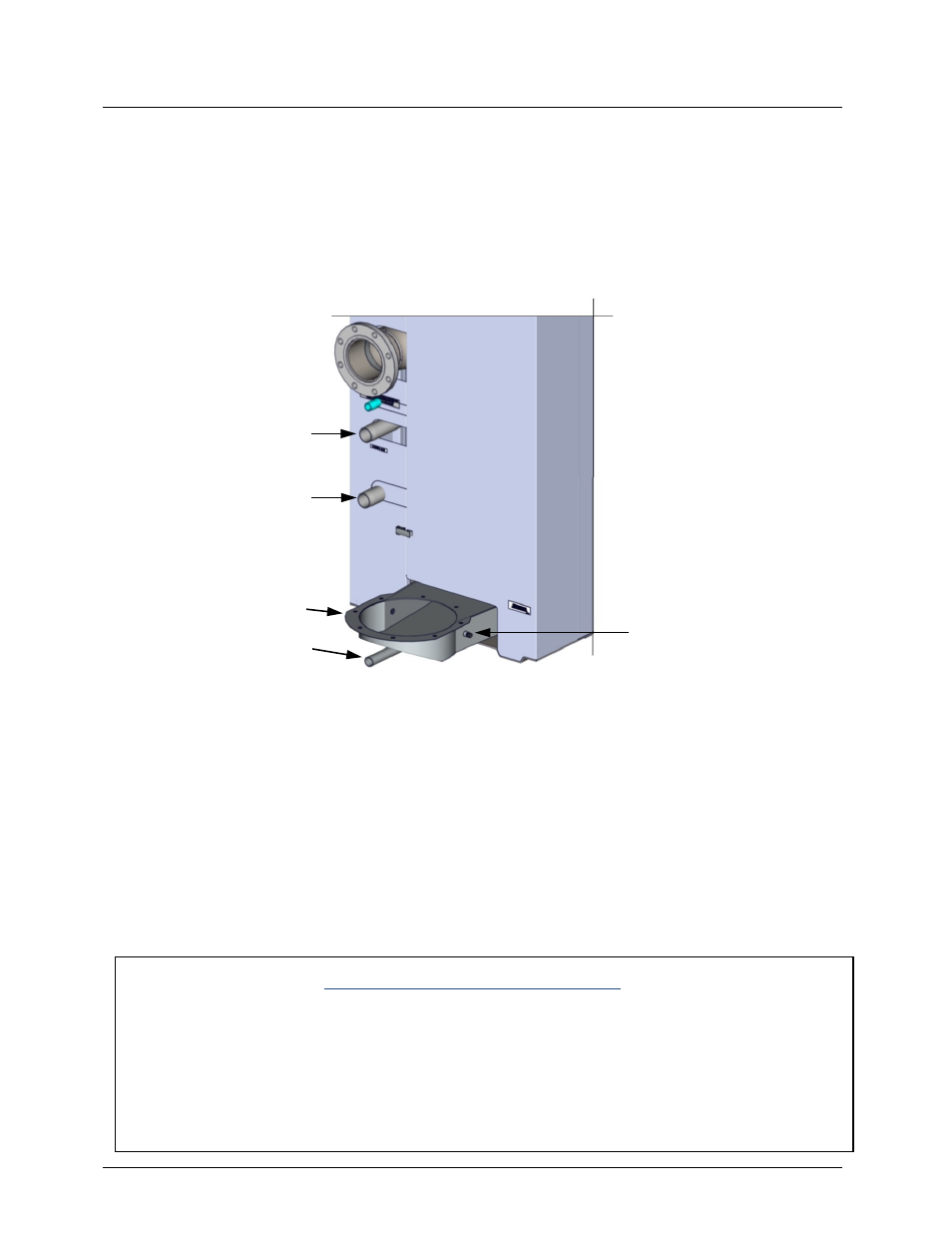
The condensate drain port is located on the exhaust manifold (Figure 2-6) at the rear of the unit.
This drain port must be connected to the condensate trap (part no. 24060), which is packed
separately within the unit’s shipping container. The condensate trap outlet connection features a
tapped 3/4” NPT drain port.
Figure 2-6. Partial Rear View – Condensate Drain Location
A sample condensate trap installation is shown in Figure 2-7. However, the actual installation
details for the trap will vary depending on the available clearances, housekeeping pad height/
dimensions and other prevailing conditions at the site. The following general guidelines must be
observed to ensure proper condensate drainage:
• The condensate trap inlet (Figure 2-7) must be level with, or lower than the exhaust
manifold drain port.
• The base of the condensate trap must be supported to ensure that it is level (horizontal).
• The trap must be removable for routine maintenance. AERCO recommends that a union
be utilized between the exhaust manifold condensate drain port and the trap inlet port.
While observing the above guidelines, install the condensate trap as follows:
Condensate Trap Installation
1.
Connect the condensate trap inlet to the exhaust manifold drain connection by sliding the
trap inlet onto the drain port. Tighten the thumbscrew on the trap inlet.
2.
At the condensate trap outlet, install a stainless steel or PVC 3/4” NPT nipple.
3.
Connect a length of 1” I.D. polypropylene hose to the trap outlet and secure with a hose
clamp.
4.
Route the hose on the trap outlet to a nearby floor drain.
ANALYZER PORTS
(2, one on each side)
EXHAUST
MANIFOLD
CONDENSATE
DRAIN
2” NATURAL GAS
INLET
2” PROPANE INLET