5 supply and return piping, 1 pressure relief valve installation – AERCO BMK 6000 Dual Fuel User Manual
Page 20
Benchmark 6000 DF Installation, Operation & Maintenance Manual
CHAPTER 2 – INSTALLATION
Page 20 of 219
AERCO International, Inc. • 100 Oritani Dr. • Blauvelt, NY 10913
OMM-0096_0B
03/21/2014
Ph.: 800-526-0288
GF-141
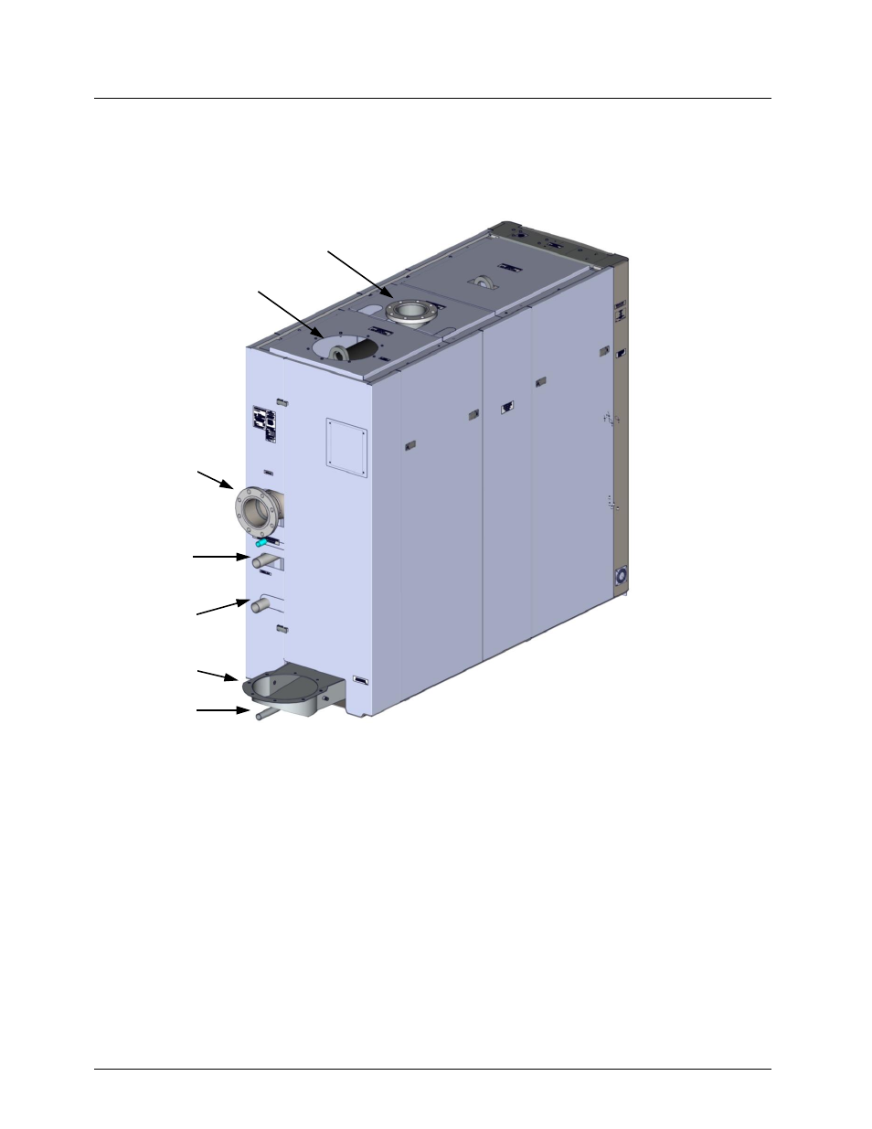
2.5 SUPPLY AND RETURN PIPING
The Benchmark boiler utilizes 6” flanged fittings for the water system supply and return piping
connections. The physical location of the supply and return piping connections are shown in
Figure 2-4. For dimensional data, refer to Drawing AP-A-901 in Appendix F.
Figure 2-4. Supply and Return Locations
2.6 PRESSURE RELIEF VALVE & PRESSURE/TEMPERATURE INDICATOR
INSTALLATION
2.6.1 Pressure Relief Valve Installation
Depending on the pressure required, the Benchmark 6000 is supplied with either a single 2” or
two (2) 1¼“ ASME rated Pressure Relief Valves. The pressure rating for the relief valve must be
specified on the sales order. Available pressure ratings range from 30 psi to 160 psi, depending
on pressure vessel maximum rated pressure. Each pressure relief valve is furnished as a kit
(92102-Tab) which consists of the relief valve for the pressure rating specified on the Sales
Order. The appropriate size reducing bushing and nipple are also included in the kit. The
pressure relief valves, nipples and bushings are connected to 45º street elbows already installed
on the heat exchanger of the boiler. The relief valves are installed on the top of the boiler as
shown in Figure 2-5A. A suitable pipe joint compound should be used on all threaded
6” WATER
OUTLET
AIR INLET
6” WATER
INLET
2” NATURAL
GAS INLET
EXHAUST
MANIFOLD
CONDENSATE
DRAIN
2” PROPANE
INLET