Connecting the power/data cable, To connect the gpsmap to a power source, Appendix – Garmin 210 User Manual
Page 75
Attention! The text in this document has been recognized automatically. To view the original document, you can use the "Original mode".
Connecting the power/data cable
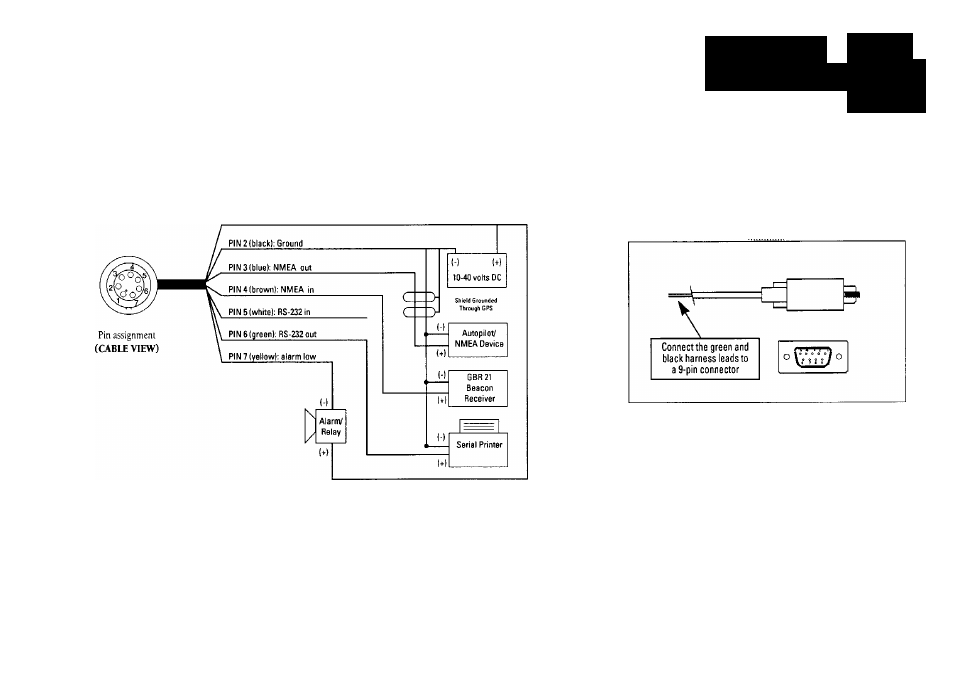
The power/data cable connects the GPSMAP system to a 10-40 volt DC
power source and provides interface capabilities for connecting NMEA devices,
a serial printer, and an external alarm (see section 10 for interface operation
details). The color code in the diagram below indicates the appropriate
harness connections.
PIN 1 (red): 10-40 mils DC
To connect the GPSMAP to a power source:
1. Connect the RED harness lead to the positive side of a 10-40voltDC power
source. Make sure the power lead has an in-line 2-amp fuse installed.
2. Connect the BLACK harness lead to a ground strip or the negative side of a
10-40 volt DC power source.
APPENDIX
Wiring InstaUatioii
SECTION
B
The GPSMAP system will also interface to a RS-232
serial printer to print speed and course information
and to an external alarm device..
To connect to a serial printer, connect the
GREEN
and BLACK (ground) harness leads to a standard
9-pin V connector. See section 10 for selecting
printing intervals and baud rates.
To connect an external alarm, connect the ground
side of the alarm device or relay to the YELLOW
harness lead.
65