12 analog output calibration, 13 test mode, 12 analog output calibration 12.13 test mode – Rice Lake 520 HMI Digital Weight Indicator Installation Manual User Manual
Page 92
Appendix
86
12.12 Analog Output Calibration
The following calibration procedure requires a multi
meter to measure voltage or current output from the
analog output module. If the option is not already
installed, see Section 2.4 on page 8.
Note
The analog output must be calibrated after the
indicator itself has been configured
(Section 3.0) and calibrated (Section 4.0).
9999999
9999999
"-(065
%*(*/
4&5154
9999999
130(3.
1'03.5
4&3*"-
$"-*#3
9999999
$0/'*(
'03."5
4063$&
(3044
0''4&5
&33"$5
'6--4$
)0-%
OVNCFS
.*/
OVNCFS
."9
58;&30
/&5
5841"/
;&304$
9999999
7&34
OVNCFS
OVNCFS
.*/ /&(
."9/&(
0/
0''
0/
0''
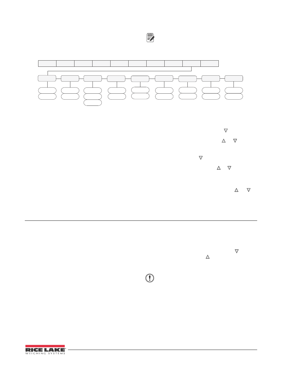
Figure 12-4. Analog Output Menu
1. Enter setup mode and go to the ALGOUT
menu (see Figure 12-4):
•
Set OFFSET to 0% for 0–10 V output,
20% for 4–20 mA output
•
Set mode select jumper on analog output
board to “V” for 0-10 V output, or “I” for
4-20 mA output
•
Set MIN to lowest weight value to be
tracked by the analog output
•
Set MAX to highest weight value to be
tracked by the analog output
2. Connect multimeter to connector J1 on the
analog output board:
•
For voltage output, connect voltmeter
leads to pins 3 and 4
•
For current output, connect ammeter leads
to pins 1 and 2
3. Adjust zero calibration: Scroll to the
TWZERO parameter. Press to view zero
value, then check voltage or current reading on
multimedia. Press and hold or to adjust
the zero value up or down.
4. Adjust span calibration: Scroll to the TWSPAN
parameter. Press to view span value, then
c h e c k v o l t a g e o r c u r r e n t r e a d i n g o n
multimeter. Press and hold or to adjust the
span value up or down.
5. Final zero calibration: Return to the TWZERO
parameter and verify that the zero calibration
has not drifted. Press and hold or to
re-adjust the zero value as required.
6. Return to normal mode. Analog output
function can be verified using test weights.
12.13 Test Mode
In addition to normal and setup modes, test mode
provides a number of diagnostic functions for the
520
,
including:
•
Display raw A/D count
•
Display digital input states
•
Reset configuration parameters to default
values
•
Clear non-volatile (battery backed) storage
•
Set analog output state to zero or full scale
•
Set A/D offset and gain calibration
•
Print configuration
To enter test mode, press and hold the setup switch
until the front panel display shows the word
TEST
. After
a b o u t t h r e e s e c o n d s , t h e t e s t m o d e d i s p l a y
automatically shifts to the first test menu function,
A/DTST.
Figure 12-5 on page 87 shows the Test Menu structure;
Figure 12-6 shows the front panel key functions in test
mode. Note that, because the Test Menu functions are
all on a single menu level, the
GROSS/NET
( ) key has
no function. Press the
ZERO
( ) key to exit test mode.
Table 12-12 on page 87 summarizes the test menu
functions.
Important
A/D calibration functions, ADOFFS and
ADGAIN, must be used only by qualified
service personnel, and only after
replacing A/D converter components.
Improper A/D calibration may render the
indicator unusable.