3 enclosure disassembly, 4 cable connections, 3 enclosure disassembly 2.4 cable connections – Rice Lake 520 HMI Digital Weight Indicator Installation Manual User Manual
Page 14
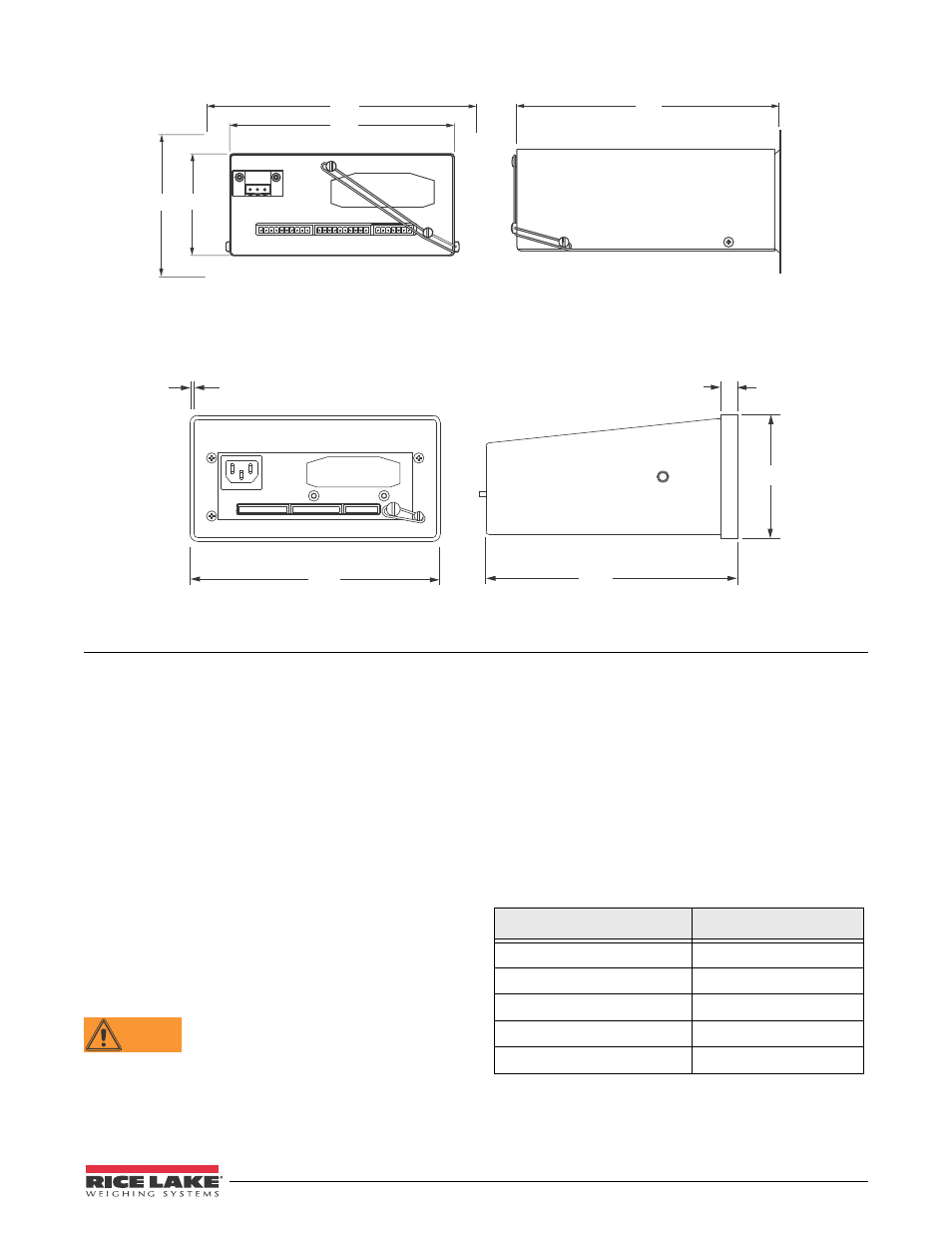
7.29
6.22
2.75
7.36
3.88
Installation
8
Figure 2-3. 520 Stainless Steel Panel Mount Dimensions
7.55
.12
3.80
7.27
.50
Figure 2-4. 520 Desktop Dimensions
2.3
Enclosure Disassembly
Enclosure disassembly is not required to make
connections for load cells, serial communications, or
digital I/O. These connectors are all externally
mounted on the back of the indicator.
Stainless Steel Panel Mount Model Disassembly
To remove the enclosure cover of the 520 panel mount
model indicator, loosen and remove four Phillips head
screws on outside of indicator (see Figure 2-9 on
Desktop Model Disassembly
To remove the enclosure cover of the 520 desktop
model indicator, loosen and remove four Phillips head
screws on back of indicator. Slide the enclosure off of
the interior tray assembly of the indicator (see
WARNING
The
520
has no on/off switch. Before
opening the unit, ensure the power cord is
disconnected from the power outlet.
2.4
Cable Connections
The
520
has three external connectors, a terminal
connector for the power cord (the desktop has inlet
connector), and a cutout for installed options.
Enclosure disassembly is not required to make
connections to load cells, communications, digital
inputs, and digital outputs. These connectors are all
externally mounted on the back of the indicator.
Cable connections for installed options use a cable
assembly with a cover plate over the backplate cutout.
See Table 2-1 for option card addendum part numbers.
Table 2-1. Option Card Addendum
Option
Addendum Part Number
BCD
76127
Remote I/O
69950
DeviceNet
69949
Profibus DP
69948
Ethernet
72117