6 data formats, 1 continuous output serial data format, 2 demand output serial data format – Rice Lake 520 HMI Digital Weight Indicator Installation Manual User Manual
Page 82: 3 rs-485 data formats, Continuous output serial data format, Demand output serial data format, Rs-485 data formats, Stx>
Appendix
76
12.6 Data Formats
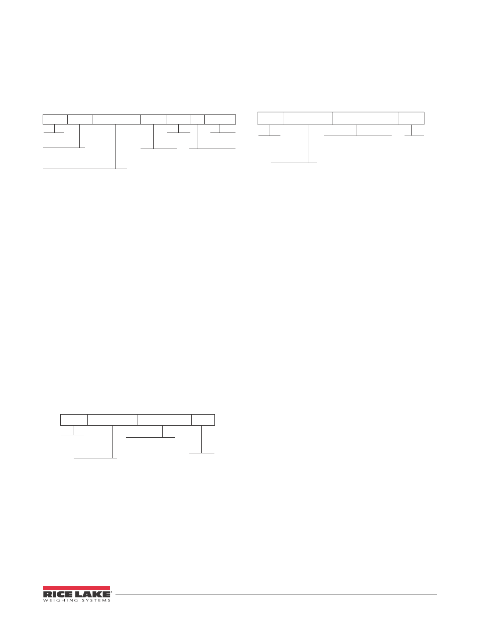
12.6.1 Continuous Output Serial Data Format
If continuous transmission is configured for the EDP or
printer port (STREAM parameter on the SERIAL
menu), the
520
sends data using the Consolidated
Controls serial data format shown in Figure 12-1:
ASCII 02
decimal
Polarity:
< space > = Positive
<–> = Negative
W eight: 7 digits, right-justified,
dummy
zer o es, d ecimal point w ith no leadin g
zer oes except for leading zer o immediately
pr eceding the decimal point. Leading
zer oes transmitted as spaces.
L = pounds
K = kilogram s
T = tons (T
, TN,
LT )
O = ounces
G = grams
< space > = GN,
TROYOZ, TROYLB,
or NONE
G = Gr oss
N = Net
Status:
< space > = valid
I = Invalid
M = Motion
O = Over/under range
or
Figure 12-1. Continuous Output Serial Data Format
12.6.2 Demand Output Serial Data Format
When demand mode is configured for the EDP or
printer port in the setup menus (PRNDEST on the
SERIAL menu), the
520
uses a data string formatted for
a basic ticket printout. The particular ticket format
printed depends on the indicator configuration.
You can use the EDP port or keypad to fully customize
the ticket to work with a wide variety of printers,
scoreboard displays, and other remote equipment. See
Section 12.0 on page 73 for more information on
custom print formats.
12.6.3 RS-485 Data Formats
The
520
has a built-in RS-485 software protocol which
is enabled when you assign a non-zero address to the
indicator. Valid RS-485 addresses must be in the range
1–255; the address is specified on the ADDRESS
parameter on the SERIAL menu.
All remote commands are initiated using the data
format shown in Figure 12-2:
ASCII 02
decimal
Addr ess of the
r eceiving indicator
EDP serial command
NOTE: Host must send
Failur e to use
r enders all indicators unable to
r espond to serial commands
ASCII
13 decimal
Figure 12-2. RS-485 Send Data Format
If the initiating device address matches the port address
of a
520
on the RS-485 network, that indicator
responds. For example, with demand outputs, or in
response to a XG command, the responding indicator
uses the format shown in Figure 12-3:
ASCII 02
decimal
Addr ess of the
transmitting indicator
EDP Serial Command
ASCII 13
decimal
Figure 12-3. RS-485 Respond Data Format
Example:
To send the XG command from an ASCII
terminal to an indicator at address 65 (decimal) on the
RS-485 network, use the format shown in Figure 12-2.
•
The keyboard equivalent for the start-of-text
(
S T X
) c h a r a c t e r i s
C O N T R O L - B
( s e e
•
The indicator address (65) is represented by an
upper case “A”.
•
The carriage return (CR) character is generated
by pressing the
ENTER
key.
Therefore, to send the XG command to the indicator at
address 65, enter the following at the terminal:
C
TRL
-B A XG
ENTER
.
The indicator will respond to the XG command with
the gross weight and units. See Section 9.0 on page 50,
for other commands that can be used.