5 ethernet communications, 6 digital i/o, Ethernet communications – Rice Lake 520 HMI Digital Weight Indicator Installation Manual User Manual
Page 17: Digital i/o, Table 2-4
11
520 Indicator Installation Manual
T h e E D P p o r t s u p p o r t s R S - 2 3 2 o r R S - 4 8 5
communications; the printer port provides active 20
mA output and full-duplex RS-232 communications.
Both ports are configured using the SERIAL menu. See
Section 3.0 on page 17 for configuration information.
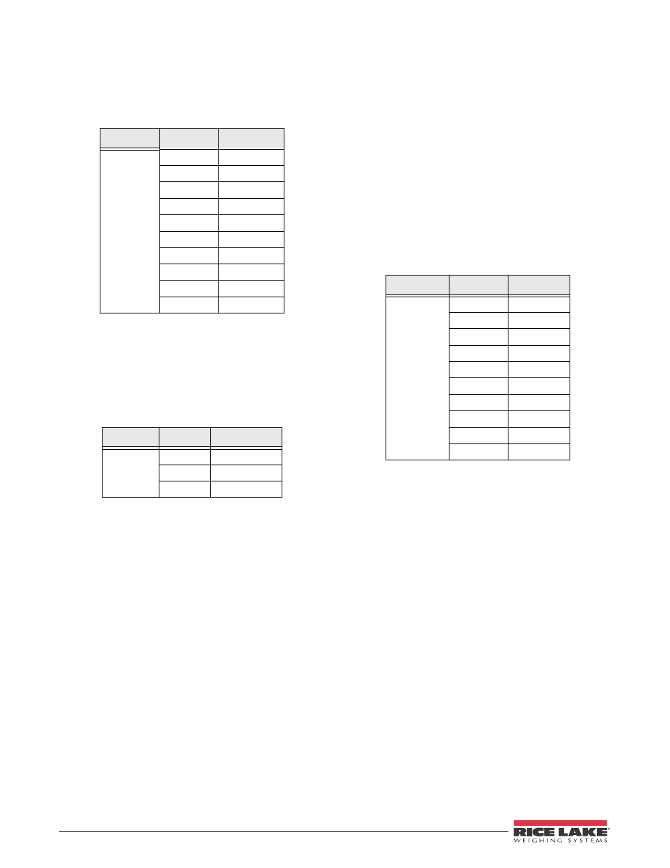
Table 2-4. J5 Pin Assignments
Connector
Pin
Signal
J5
1
EDP TxD
2
GND
3
EDP RxD
4
Printer TxD
5
Printer RxD
6
–20 mA TxD
7
+20 mA TxD
8
RS-485A
9
RS-485B
10
GND
2.4.5
Ethernet Communications
Communications port J8 on the 520 CPU board is a
special internal connection to the EDP port for RS-232
communications at up to 19200 bps. J8 can be used for
wiring the Ethernet option card (PN 71986) to the
520
indicator.
Table 2-5. J8 Pin Assignments (Ethernet)
Connector
Pin
Signal
J8
1
TXD
2
GND
3
RXD
2.4.6
Digital I/O
Digital inputs can be set to provide many indicator
functions, including all keypad functions. Digital
inputs are active (on) with low voltage (0 VDC),
inactive (off) at 5 VDC. Use the DIG IN menu to
configure the digital inputs.
Digital outputs are typically used to control relays that
drive other equipment. Outputs are designed to sink,
rather than source, switching current. Each output is a
normally open collector circuit, capable of sinking 250
mA when active. Digital outputs are wired to switch
relays when the digital output is active (low, 0 VDC)
with reference to a 5 VDC supply.
Use the SETPTS menu to configure digital outputs.
Table 2-6 shows the pin assignments for connector J4.
Table 2-6. J4 Pin Assignments (Digital I/O)
Connector
Pin
Signal
J4
1
GND
2
DI1
3
DI2
4
DI3
5
DO1
6
DO2
7
DO3
8
DO4
9
GND
10
+5V