1 load cells, 2 panel mount parts kit, pn 82427, 3 serial communications – Rice Lake 520 HMI Digital Weight Indicator Installation Manual User Manual
Page 15: 4 condec umc2000 conversion connections, Load cells, Panel mount parts kit, pn 82427, Serial communications, Condec umc2000 conversion connections, J4 j5
9
520 Indicator Installation Manual
2.4.1
Load Cells
To attach cable from a load cell or junction box, route
the cable to the external J6 connector. Wire the load
cell cable from the load cell or junction box to
connector J6 as shown in Table 2-2. If using 6-wire
load cell cable (with sense wires), open the enclosure
cover (see Section 2.3) and remove jumpers JP1 and
JP2 before reinstalling connector J6. For 4-wire
installation, leave jumpers JP1 and JP2 on.
Table 2-2. J6 Pin Assignments
Connector
Pin
Function
J6
1
+SIG
2
–SIG
3
+SENSE
4
–SENSE
5
+EXC
6
–EXC
7
SHIELD
For 6-wire load cell connections, remove
jumpers JP1 and JP2.
2.4.2
Panel Mount Parts Kit, PN 82427
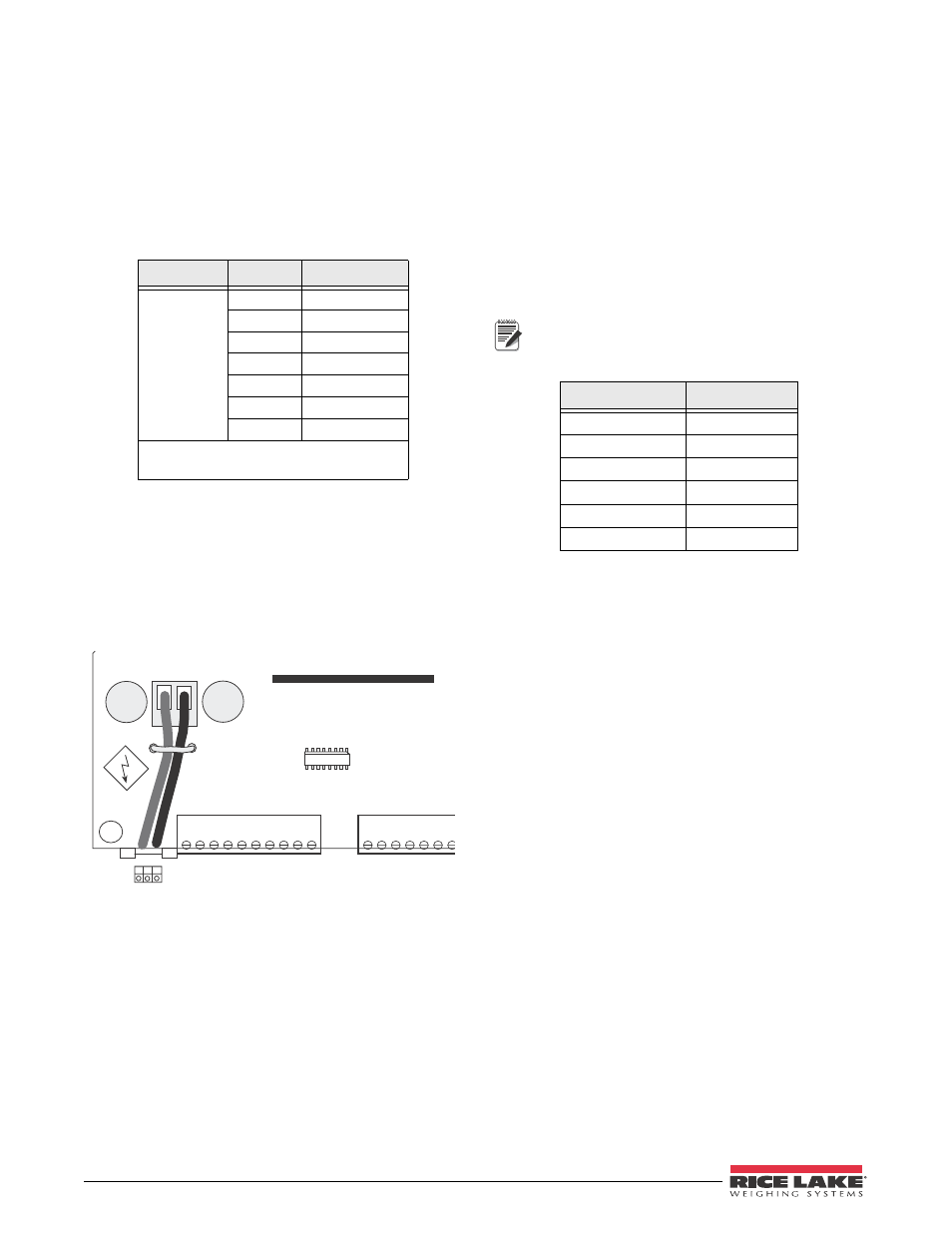
Power connections to the 520 Panel Mount are shown
below. This only applies to the panel mount.
Part number 15888 is used to connect AC power to
balloon number 12 of Figure 2-9 on page 15.
Attach the wires per the diagram shown below.
RICE LAKE WEIGHING SYSTEMS
U1 9
F2
J4
J5
F1
J
1
2
3
4
5
6
7
1
2
3
4
5
6
7
8
9
10
Hot
AC Gr
ound
Neutral
Figure 2-5. AC Power Cord Connection Location
2.4.3
Serial Communications
Attach serial communications cables to external
connector J5. Connector J5 provides connections for
the EDP (Electronic Data Processing) port, printer port,
20 mA current loop transmit signals, and RS-485
signals. Table 2-4 shows the pin assignments for
connector J5.
2.4.4
Condec UMC2000 Conversion Connections
See Table 2-3 for information on load cell connections
when replacing the Condec UMC2000 indicator with
the 520 desktop model indicator.
Note
Pin-outs and connectors for serial
communications and BCD are the same for
both units.
Table 2-3. Load Cell Pin-outs
UMC2000
520 Desktop
1
5
2
2
3
1
4
6
5
3
6
4