5 analog output card installation, 6 cpu board removal – Rice Lake 520 HMI Digital Weight Indicator Installation Manual User Manual
Page 18
Installation
12
2.5
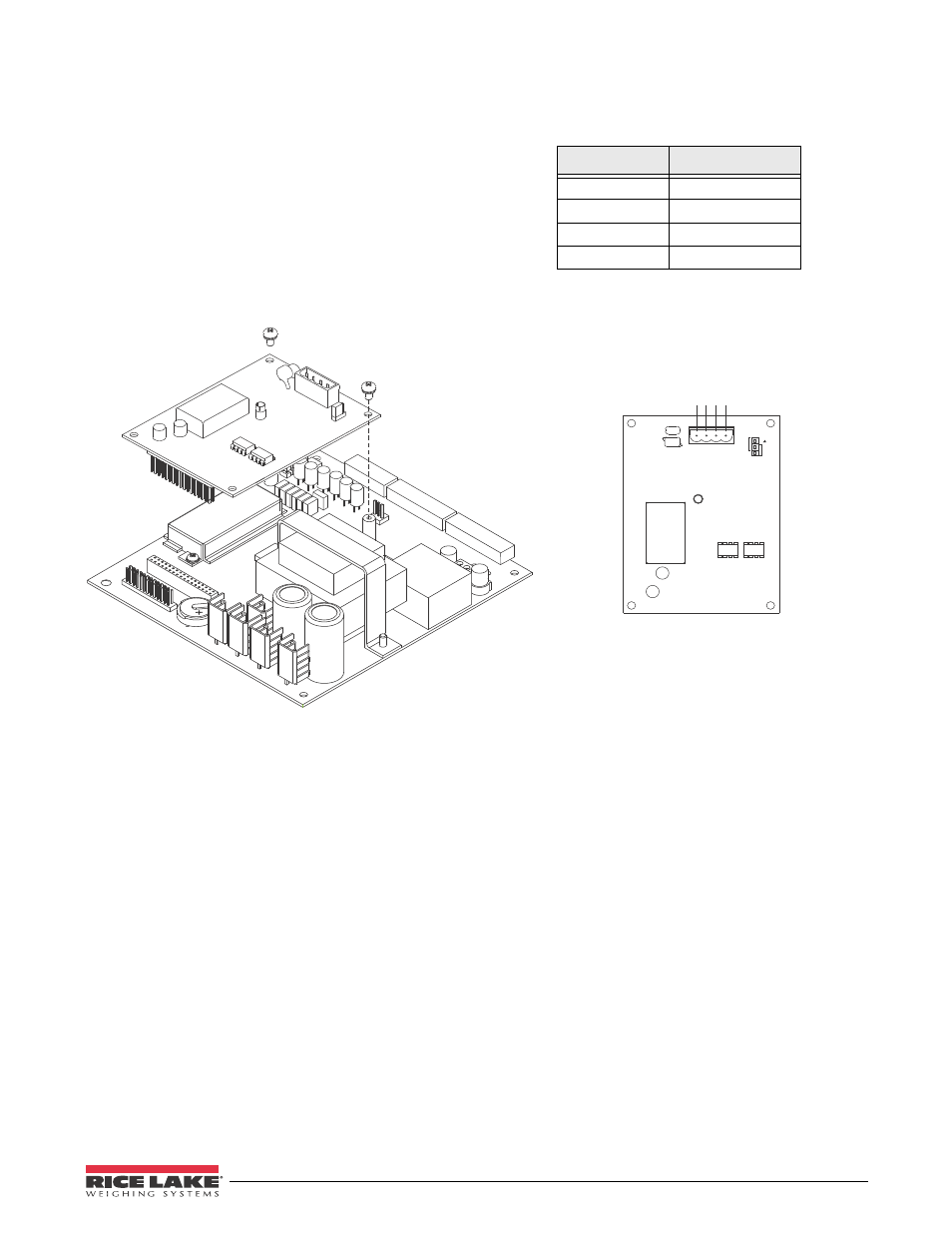
Analog Output Card Installation
To install or replace the analog output option card,
open the
520
enclosure. See Table 2-1 on page 8 for
option card addendum part numbers.
Mount the analog output card on its standoffs in the
location shown in Figure 2-7 on page 12 and plug the
card input into connector J2 on the
520
board. Connect
the output cable to the analog output card as shown in
Table 2-7. Set the mode select jumper for voltage or
current output.
Use the ALGOUT menu to configure the analog output
card when cabling is complete. See Section 12.12 on
page 86 for analog output calibration procedures.
Table 2-7. Analog Output Card Pin Assignments
Pin
Signal
1
+ Current Out
2
– Current Out
3
+ Voltage Out
4
– Voltage Out
.PEF4FMFDU
+VNQFS
7
7
*
*
*
7
Figure 2-7. Analog Output Card Installation
2.6
CPU Board Removal
If you must remove the
520
CPU board, use the
following procedure:
1. Disconnect power to the indicator.
2. Unplug connectors J6 (load cell cable), J5
(serial communications), and J4 (digital I/O).
If an analog output board is installed,
disconnect the analog output cable. See
Figure 2-6 on page 10 for connector locations.
3. Unplug any installed option cards from the
CPU board.
4. Remove brown and blue wire from J3
connector.
5. Unplug ribbon cable from J1.
6. Remove four Phillips head screws located in
each corner of CPU board.
7. Carefully lift CPU board out of enclosure.
To replace the CPU board, reverse the above
procedure. Be sure to reinstall cable ties to secure all
cables inside the indicator enclosure.