2 menu structures and parameter descriptions, Section 3.2 – Rice Lake 520 HMI Digital Weight Indicator Installation Manual User Manual
Page 25
TU
-FWFM
1BSBNFUFS
%FGBVMUWBMVF
OE
-FWFM
1BSBNFUFS
7BMVF
7BMVF
7BMVF
TU
-FWFM
1BSBNFUFS
OE
-FWFM
1BSBNFUFS
8IFONPWJOHUISPVHIWBMVFTCFMPXUIFmSTUNFOVMFWFM QSFTT
UPSFUVSOUPUIFMFWFM
BCPWF1SFTT
PS
UPNPWFUPUIFOFYUQBSBNFUFSPOUIFMFWFMBCPWF
19
520 Indicator Installation Manual
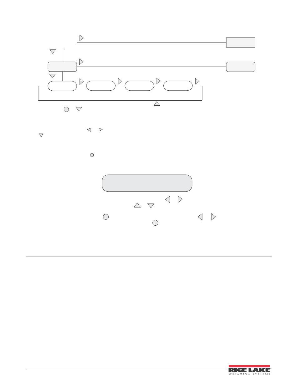
Figure 3-3. Setup Mode Menu Navigation
To select a parameter, press or to scroll left or right until the desired menu group appears on the display, then
press to move down to the submenu or parameter you want. When moving through the menu parameters, the
default or previously selected value appears first on the display.
To change a parameter value, scroll left or right to view the values for that parameter. When the desired value
appears on the display, press to select the value and move back up one level. To edit numerical values, use the
navigation keys to select the digit and to increment or decrement the value.
8IFOFEJUJOHOVNFSJDWBMVFT QSFTT
PS
UP DIBOHFUIF
EJHJUTFMFDUFE1SFTT
PS
UPJODSFNFOUPSEFDSFNFOUUIF
WBMVFPGUIFTFMFDUFEEJHJU*GBEFDJNBMQPJOUJTSFRVJSFEJOWBMVF
QSFTTUPWJFXBOENPWFEFDJNBMQPJOU1SFTT
PS UP
NPWFEFDJNBMQPTJUJPO1SFTT UPTBWFUIFWBMVFFOUFSFEBOE
SFUVSOUPUIFMFWFMBCPWF
Figure 3-4. Editing Procedure for Numeric Values
3.2
Menu Structures and Parameter Descriptions
The following sections provide graphic representations of the
520
menu structures. In the actual menu structure, the
settings you choose under each parameter are arranged horizontally. To save page space, menu choices are shown
in vertical columns. The factory default setting appears at the top of each column and is bolded. Parameters shown
surrounded by a dotted-line box only appear under the special circumstances explained under each box.
Most menu diagrams are accompanied by one or more tables that describe all parameters and parameter values
associated with that menu option. Default parameter values are shown in bold type.