Calibration, Output calibration, Co calibration – KMC Controls SAE-1152(NEW Style Board) User Manual
Page 5: Maintenance, Specifications
SAE-1101/1102/1151/1152 Carbon Monoxide (CO) Detectors
5
Installation Guide
Specifications
Range
0–300 ppm
Accuracy and Operation Conditions
±3% of reading @ 32 to 122° F
(0 to 50° C) or ±5% of reading
@ –4 to 122° F (–20 to 50° C),
15 to 95% RH, non-condensing
Response Time
< 35 seconds for 90% step
change
Warm-up Time
200 seconds
Pressure Coefficient 0.020 ±0.008% signal/mbar
Typical Coverage Area 7500 ft
2
(700 m
2
)
Power Supply
15–30 VAC/VDC (non-isolated
half-wave rectified)
Consumption
80 mA max. @ 24 VDC with all
options on, 150 mA average @
24 VAC
Protection Circuitry Reverse voltage protected
and output limited, transient
protection
Wiring Connections Screw terminals (14–22 AWG)
Output Signal
4–20 mA active (sourcing), 0–5
VDC, or 0–10 VDC, jumper
selectable
Output Drive Capability 500 ohm max. for cur-
rent output, 10K ohm min. for
voltage output
Relay Outputs (Optional)
Configuration
Two form “C” contacts (NO
and NC), 5 A @ 250 VAC, 5 A @
30 VDC, power factor = 1
Relay Trip Point Relay 1: Programmable 25 or
40–350 ppm in 10 ppm incre-
ments
Relay 2: Programmable 100–
400 ppm in 10 ppm increments
Relay Hysteresis/Deadband
Programmable 10, 15, 25, 50, or
75 ppm
Weight
1.05 lbs. (0.47 kg)
NOTE: For additional specifications, see the SAE-
1100 Series Data Sheet.
© 2009 KMC Controls, Inc.
717-019-38A
KMC Controls, Inc.
19476 Industrial Drive, New Paris, IN 46553
574.831.5250
www.kmccontrols.com; [email protected]
Maintenance
Careful installation will also ensure long-term reli-
ability and performance. Remove dust as necessary
from holes. Clean with a soft, damp cloth and mild
soap.
Calibration
Output Calibration
If necessary, the current and voltage outputs can be
calibrated as described previously in the Menu Con-
figuration section by using the buttons and a meter
connected to the output. See the Set-Up section.
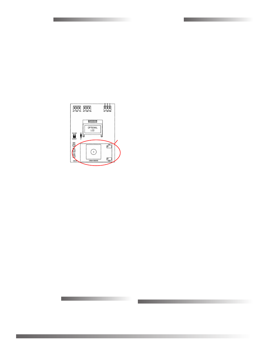
CO Calibration
The detector features a precalibrated, replaceable
sensor module. The sensor module can be un-
plugged and a new calibrated module installed in its
place. To swap sensor modules:
1. Disconnect the
device power.
2. Remove the screws
and cover.
3. Unplug the old
sensor module.
4. Install the new
module, ensuring
the module’s
connector is
properly aligned.
5. Reinstall the cover and screws.
6. Reconnect power.
Making adjustments or applying gas to the transmit-
ter is unnecessary using the sensor swap method.
Calibration of sensor modules should be left to expe-
rienced professionals. Calibration with gas requires
an LCD display, a bottle of gas (250 ppm CO in air), a
tank pressure regulator with flow restrictor, and the
necessary tubing with a cap to cover the sensor. KMC
Controls recommends returning sensor modules to
the factory for calibration. Having a spare, compat-
ible SAE-1100 series detector makes the swap easy,
and the spare module can be conveniently returned
to the factory for recalibration.
NOTE: Newer style boards (without LEDs) are
incompatible with older style sensor
modules and vice versa. See Models
section.
Sensor
Module