Wiring, Caution – KMC Controls SAE-1152(NEW Style Board) User Manual
Page 2
SAE-1101/1102/1151/1152 Carbon Monoxide (CO) Detectors
2
Installation Guide
Use 22 AWG shielded wiring for all connections.
Do not locate device wires in the same conduit with
wiring used to supply inductive loads.
1. Connect the positive DC voltage, or the hot
side of the AC voltage, to the terminal marked
POWER (but do not apply power until all wiring
is completed).
2. Connect the power supply common to the
terminal marked COM. The device is reverse
voltage protected and will not operate if
connected backwards.
NOTE: The detectors have a half-wave power
supply with the common the same as the
output signal common. If several units are
connected to one power supply, output
signals share the same signal common.
However, KMC recommends using a
separate transformer for each device.
CAUTION
Use caution when grounding the secondary of an
AC transformer, or when wiring multiple devices,
to ensure that the circuit ground point is the same
on all devices and the controller. See Application
Note AN0604D “Tips for connecting-volt power”
available from the KMC Controls web site or in the
SP-022 Digital Designer Guide.
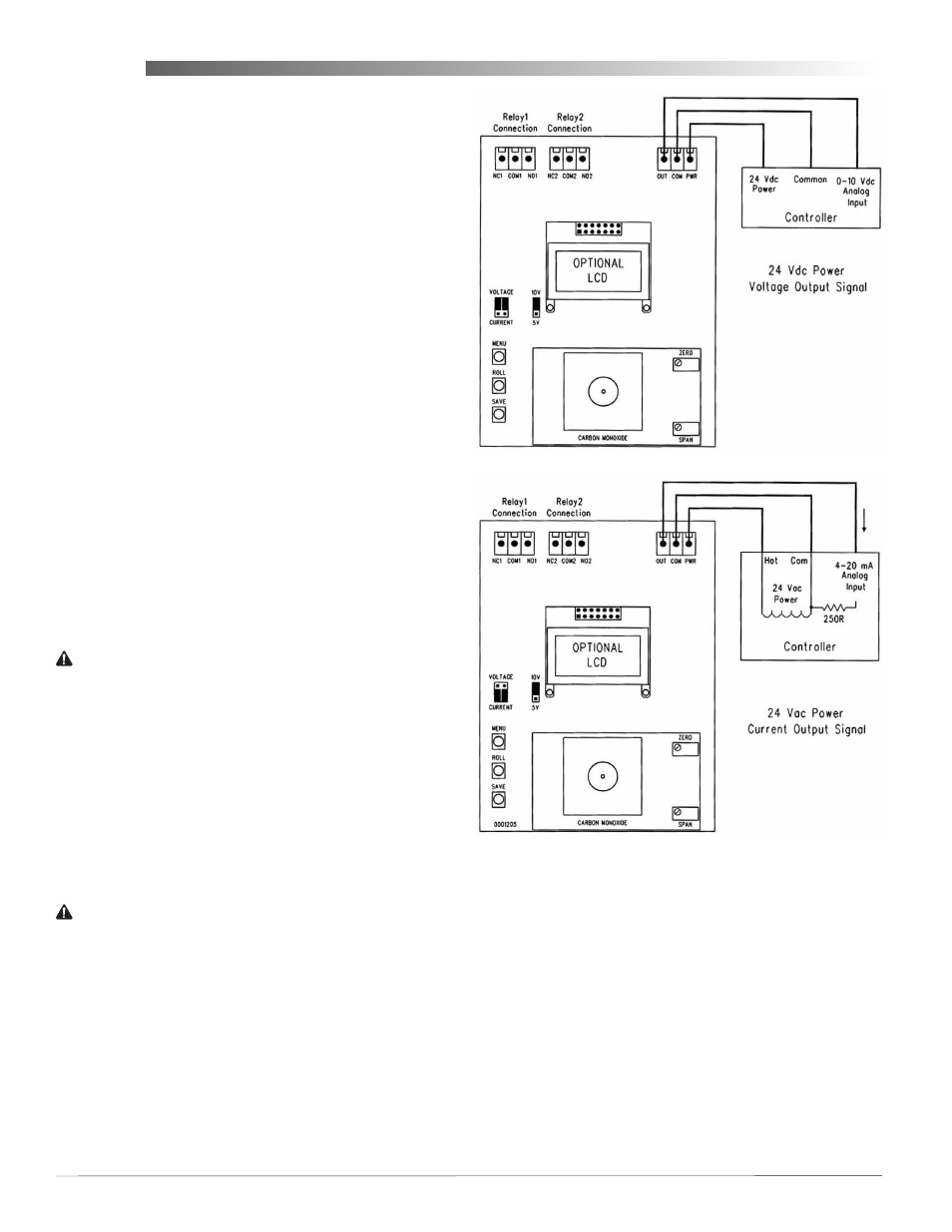
3. Select the desired analog signal output jumper
for either Current (4–20 mA) or Voltage. A second
jumper selects either 0–5 VDC output or 0–10
VDC.
CAUTION
The 4-20 mA current output signal operates in the
active mode and does not require a loop power
supply. The signal current is generated by the SAE-
1100 series detector and must not be connected to a
powered input or device damage will result.
4. Set the input jumpers/pull-up resistors on the
KMDigital or BACnet controller for the desired
active voltage or current according to the
controller’s instructions.
5. Connect the detector’s OUT terminal to the
controller’s input (referenced to the COM
terminal) according to the illustration below.
NOTE: The sets of form “C” relays feature
Normally
Open (NO), Normally Closed (NC), and
Relay Common (R.COM) terminals. The
relay output is completely isolated and
has both NO and NC signals. The R.COM
terminal is NOT connected to the signal or
power supply COMMON terminal.
NOTE: See also Application Note AN0504L
“Connecting inputs and outputs to KMC
controllers” available from the KMC
Controls web site or in the SP-022 Digital
Designer Guide.
Wiring
NOTE: These instructions apply to units
manufactured after the corresponding
dates shown in the Models list. For older
units (with a row of LEDs on the left side
of the board), see the original version of
this installation guide available on www.
kmccontrols.com.