Set-up continued – KMC Controls TPE–1464 Series(2004-2008) User Manual
Page 5
RANGE
The input pressure range is set by moving the 4-position slide switch marked RANGE. Range and Options
switches can be changed while the unit is operating.
PRESSURE RANGE
MODEL
1
2
3
4
1464-1 100 PSI 50 PSI 20 PSI 10 PSI
1464-2 200 PSI 100 PSI 40 PSI 20 PSI
1464-3 500 PSI 250 PSI 100 PSI 50 PSI
SLOW DAMPING
The switch provides an 8-second averaging for surge dampening (normally it is 4-seconds).
OUTPUT REVERSE
Reverses the output signal polarity. In reverse mode the analog output is maximum when the gage pressure
is zero and decreases as pressure increases.
OPERATION
The port is used to measure a positive pressure for normal operation such as 0 to 100 PSI
0 PSI = 4 mA
100 PSI = 20 mA.
CALIBRATION
This feature is enabled only when the detected pressure on the port is less than 5% of the full range to
protect the unit from accidental zeroing. Span calibration should not be performed in the field unless a high
quality calibrator is available.
1. Open the port to the ambient pressure or equalized at 0 pressure:
2. Press and hold the auto-zero button or provide contact closure on the ZERO terminals for at least 3
seconds.
3. Release the button or terminals and the device will calculate and store the new zero point.
Set-Up Continued
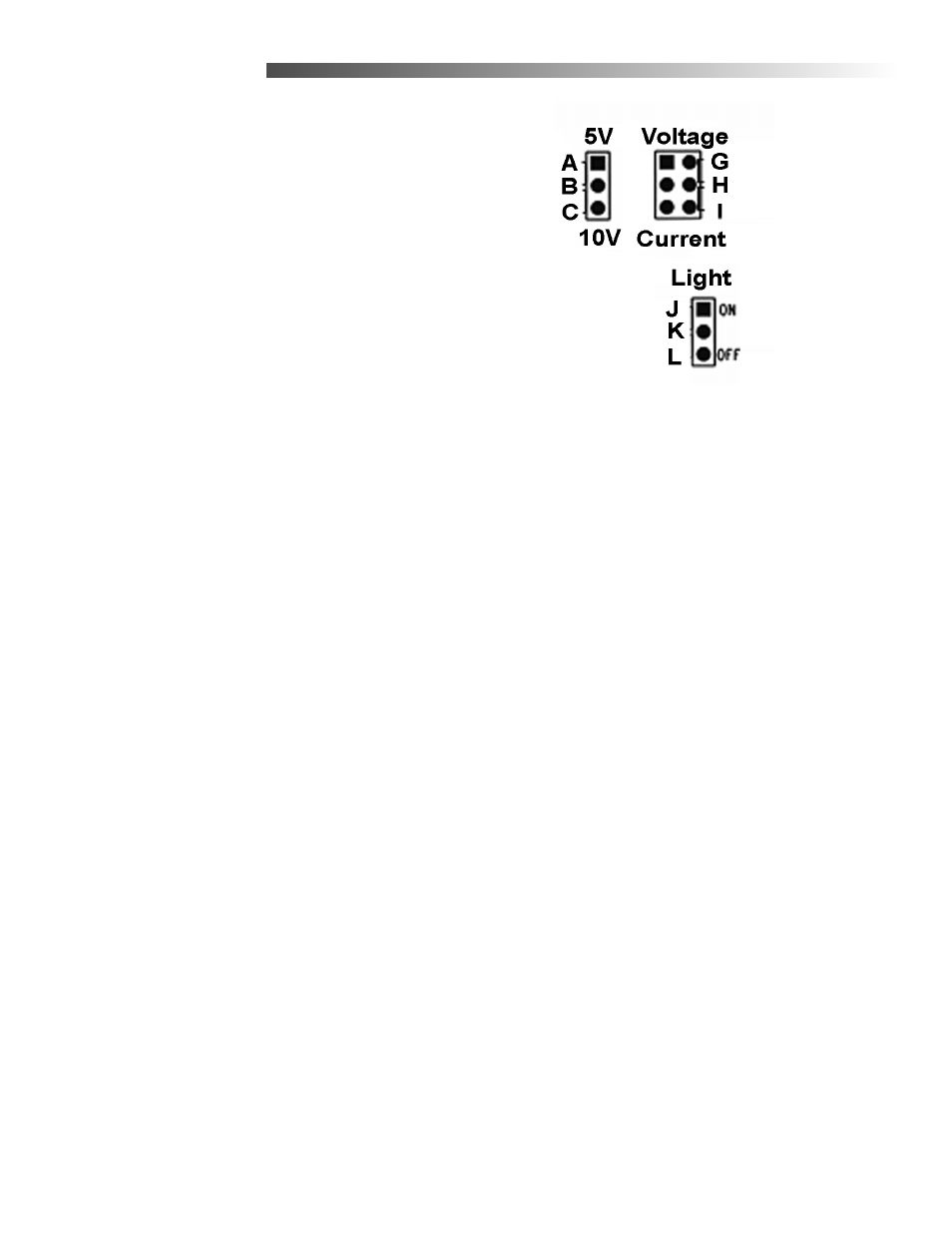
JUMPER SETTINGS
Refer to the detailed drawing for pin location, the letter
designations do not appear on the actual board.
♦
0 to 5 VDC signal
Connect A to B
♦
0 1 to 10 VDC signal
Connect B to C
♦
Voltage signal
Connect G to H
♦
Current Signal
Connect H to I
♦
For Backlight
Connect J to K
♦
No Backlight
Connect K to L