Applications, Air handler unit (ahu), Modulating heat and modulating cool – KMC Controls BAC-14xx63 Series FlexStat User Manual
Page 5
BAC-12xx63/13xx63/14xx63 Series FlexStat
5
Installation Guide, Rev. C
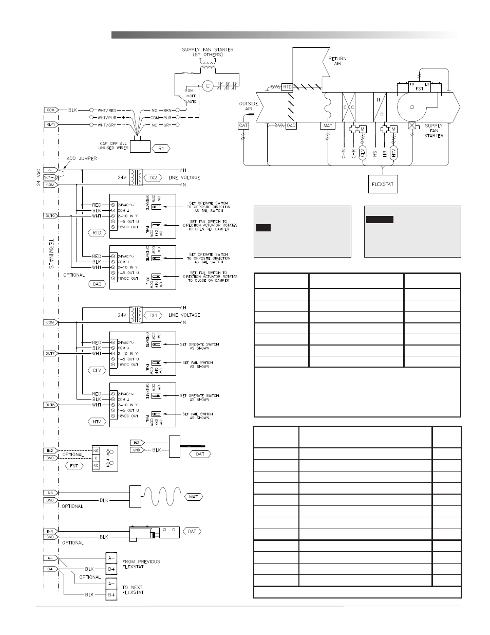
STE-1416 Duct Averaging Temp. Sensor
CSE-1102 Air Differential
Pressure Switch
MEP-5372/7252/7552/7852 Fail-Safe Actuators
XEE-6311-075/6311-100 Transformer
STE-1451 Outside Air Temp. Sensor
VEP-45xxB895/VEB-43xxxBDL Valves with MEP-5372 Fail-Safe Actuators
REE-3211 Multi-Voltage Relay
XEE-6311-075 Transformer
NOTE: EITHER FAN STATUS (FST) OR
DISCHARGE AIR TEMP (DAT) CAN
BE USED ON IN2, BUT NOT BOTH.
AHU LAYOUT
STE-1402 Duct
Sensor, Type III
Applications
Air Handler Unit (AHU)—
Modulating Heat and Modulating Cool
Input Terminals
AHU Input Connections
BACnet Objects
IN9
Opt. Remote CO
2
Sensor*
AI9
IN8
AI8
IN7
Opt. Remote Temp. Sensor*
AI7
IN4
Opt. Outside Air Temp. (OAT)**
AI4
IN3
Opt. Mixed Air Temp. (MAT)**
AI3
GND
Ground
IN2
Optional FST or DAT*
AI2
*Fan Status (FST), Discharge Air Temperature (DAT), and (not shown
on the diagram) remote temp./CO
2
sensors are optional inputs. Set
pull-up resistor switch positions appropriately (see the Input
Connections section).
**When using the optional Outside Air Damper, MAT/OAT inputs must
also be connected.
Output
Terminals
AHU Output Connections
(Modulating)
BACnet
Objects
Analog 9
Outside Air Damper (OAD/RTD)*
AO9
GND
Ground (for analog output terminals 7–9)
Analog 8
Heating Valve (HTV)
AO8
Analog 7
Cooling Valve (CLV)
AO7
Relay 6
BO6
SC 4–6
Relay 5
BO5
Relay 4
BO4
Relay 3
BO3
SC 1–3
24 VAC (for relay terminals 1–3)
Relay 2
BO2
Relay 1
Fan
BO1
*If optional Outside Air Damper is used, must also have MAT/OAT inputs.
NOTE: See also the RTU section
for 2-stage options.
APPLICATION
DEGREES SCALE: °F
APP:
ADDITIONAL SETUP
AIR HANDLER
ADDITIONAL SETUP
DAMPER
FAN
HUMIDITY
OPTIMUM START
SENSORS