Input connections, Output connections, Input connections 3 output connections 3 – KMC Controls BAC-14xx63 Series FlexStat User Manual
Page 3: Caution
BAC-12xx63/13xx63/14xx63 Series FlexStat
3
Installation Guide, Rev. C
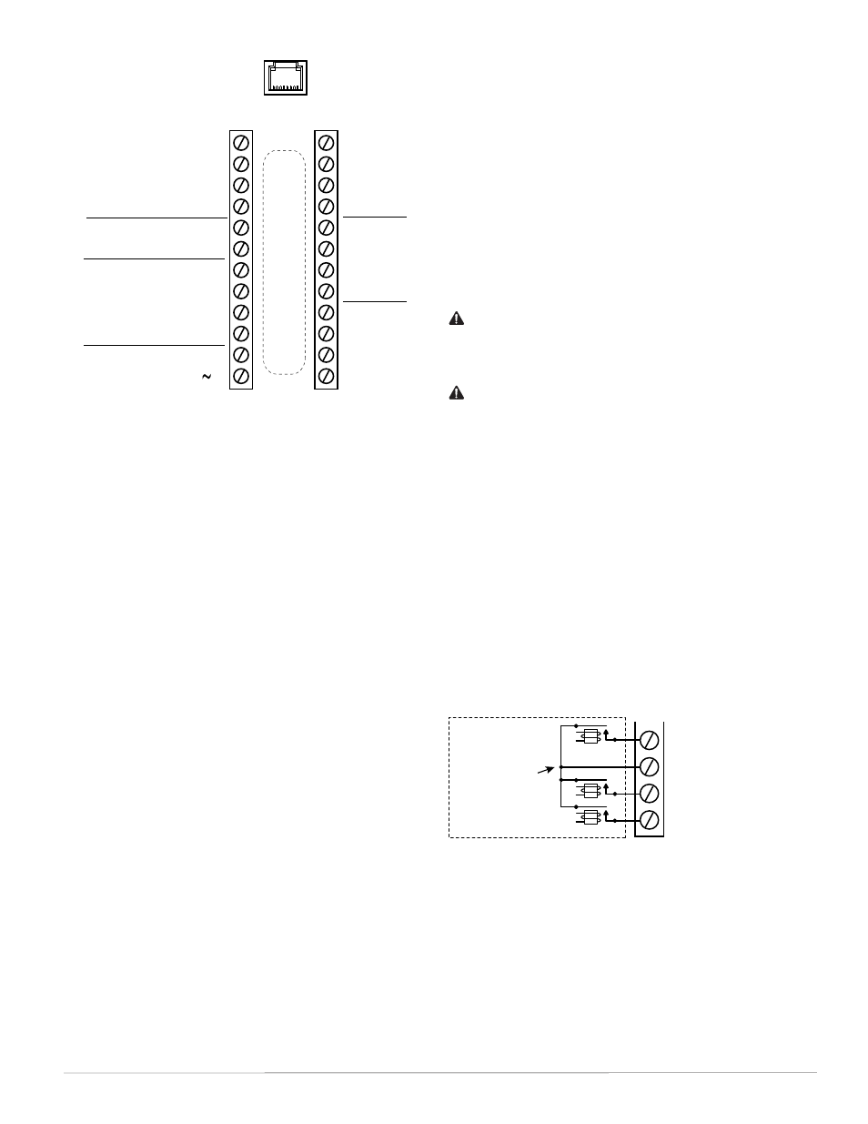
Illustration 5—(BAC-12xx63) Terminals and Connections
Input Connections
Passive input devices require pull-up resistors in the
circuit. For passive input devices (e.g., switch con-
tacts and 10K ohm thermistors) on IN2 through IN4
and IN7 through IN9, set the pull-up switches on
the back of the circuit board to the 10K position. For
active voltage devices, set the switches to the 0–12
VDC position. (See Illustrations 3 through 5.)
NOTE: Unlike the EOL switch pairs, the INPUT
switch pairs must NOT have both switch-
es set to the same direction—if one of the
pair’s switches is set to the left, for example,
the other must be set to the right (or vice
versa). ALL the input pull-up resistor
switch pairs must be fully latched in ei-
ther 10K Ohm or 0–12 VDC position even
if a switch pair has no input connected! A
single incorrect switch position may cause
errors in multiple inputs.
NOTE: Type II or III 10K ohm thermistors can
be selected by changing the menu setting
in Advanced > Inputs > Input # > Sensor
(see the Configuration section). If a remote
space temperature sensor is connected to
AI7, space temperature can be configured
for onboard, remote, averaging of the two,
the lowest reading, or the highest reading.
NOTE: FlexStat inputs do not support 1K ohm
RTDs.
Output Connections
Connect the device under control between the desired
output terminal and the related SC (Switched Com-
mon for relays) or GND (Ground for analog outputs)
terminal. (See Illustration 5).
For the bank of three relays, there is one Switched
(relay) Common connection (in place of the GND
terminal used with analog outputs). (See Illustration
6.) For the relay circuit, the phase side of the AC
should be connected to the SC terminal.
Illustration 6—Switched (Relay) Common and Relays
CAUTION
Do not mistakenly connect 24 VAC to an analog
output ground. This is not the same as a relay’s
switched common. See the backplate’s terminal
label for the correct terminal.
CAUTION
Relays are for Class-2 voltages (24 VAC) only. Do not
connect line voltage to the relays!
Do not attach a device that draws current exceeding
the FlexStat’s output capacity:
• Maximum output current for individual ANA-
LOG outputs (7–9) is 20 mA @ 12 VDC (each).
• Max. output current is 1 A for individual
RELAYS @ 24 VAC/VDC or a total of 1.5 A per
bank of 3 relays (relays 1–3 and 4–6).
IN9
IN8
GND
IN7
+B
–A
IN4
IN3
GND
IN2
Common/–/C
Phase/ /R
Analog 9
GND 7–9
Analog 8
Analog 7
Relay 6
SC 4–6
Relay 5
Relay 4
Relay 3
SC 1–3
Relay 2
Relay 1
Outputs
(Wir
ing Cutout in Bac
kplate)
MS/TP
Network
Inputs
24 VAC
(Wiring is
dependent on
application)
Inputs
IP/Ethernet
Network
(Optional)
NOTE: IN1 and IN5–6 are
reserved for internal sensors
NOTE: SC = Switched
(relay) Common
NOTE: To use a 4–20 current loop input or map
analog inputs as binary values, see the
FlexStat Application Guide.
NOTE: To use a remote SAE-10xx CO
2
sensor, see
the FlexStat Operation Guide.
NOTE: For more information on wiring specific
applications (AHU, FCU, HPU, RTU), see
the Applications section starting on page
5. (These applications are the packaged
programs selectable from the Advanced
> Application menu in the BAC-1xxx63C
models.)
NOTE: On BAC-13xxxx/14xxxx models, terminals
are rotated 90° CCW.
Relay 3
(or 6)
SC (Phase) 1–3
(or 4–6)
Relay 2
(or 5)
Relay 1
(or 4)
One Switched
Common
Connection
Per Bank of
Three
Normally
Open Relays