Elecraft P3 High-Performance Panadapter Manual User Manual
Page 56
56
Plug the free end of the ribbon cable into P504 on the I/O board or, if the P3SVGA board is installed, into
P102 on the P3SVGA board. Be sure the red edge is at the Pin 1 end of the connector (the end nearest the
bottom). To avoid stressing the board, support it with your fingers while mating the connector by placing your
fingers on the side of the board opposite the connector and squeezing the connector in place with your thumbs.
Be sure the connectors are properly aligned so that all pins engage the cable connector just as you did on the
display board (see Figure 19).
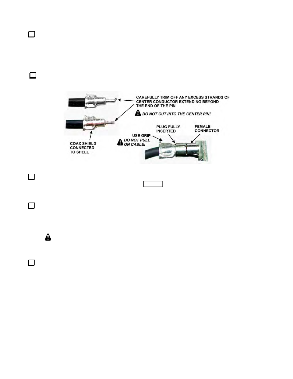
Locate the TMP coaxial cable. Plug one end into J902 on the RF board and the other end into RF IN, J100
on the front panel board. The connectors simply press into the sockets and are held in place by friction. If a
connector refuses to engage, check for excess loose center conductor wires (see Figure 20).
Figure 20. TMP Connectors.
Check the position of the jumper block on P502 on the I/O board (in the top corner just above the ribbon
connector) and place it according to how you want the
P O W E R
switch to operate (see Configuration on page
30).
Inspect the inside surface of the side covers to ensure there is bare metal around each screw hold for good
contact with the angle brackets or 2D fasteners. Be sure that you clean away paint on the inside surface, not the
outside (see Figure 10, page 49). The screws holes are not countersunk on the inside surface of the panels. They
are countersunk on the outside surface.
IMPORTANT: Do not over-tighten the case screws in the following step or when
mounting the top cover later. You can strip the threads or damage and scratch the screw
heads.
Mount the side panels, using five 3/16” (4.8 mm) flat head screws in each panel. The center top hole will be
filled when you install the top cover later. Although the panels are identical, they only fit one way so the holes
align with the fasteners. If a screw binds or does not line up properly, loosen the other screws holding the 2D
fastener or the screw into the L- bracket so it can move slightly for better alignment. If a side panel seems
pushed away from the bottom cover at the center, check the L-bracket carefully. The usual cause is an L-bracket
installed incorrectly (see Figure 10).