Theory of operation – Elecraft P3 High-Performance Panadapter Manual User Manual
Page 37
37
Theory of Operation
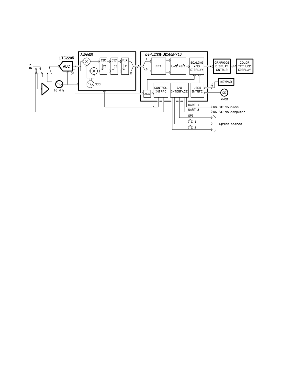
The P3 is a true software-defined receiver the input goes through an amplifier directly to a 60 Msample/sec
analog-to-digital converter (ADC), with all tuning, signal processing and the user interface under software
control. The Analog Devices AD6620 digital down-converter includes a numerically-controlled oscillator
(NCO) which acts as a local oscillator and a pair of multipliers that act as a quadrature mixer that down-convert
a band of frequencies to a pair of baseband in-phase and quadrature (I/Q) signals. Those signals then pass
through three decimating low-pass filters to generate a lower-bandwidth, lower-sample-rate I/Q signal that is
passed to a Microchip dsPIC digital signal processor/controller.
The dsPIC further processes the signal for presentation on the 480x272-pixel color TFT LCD display. The
"circuitry" shown inside the processor box in the block diagram is actually implemented as software routines.
The FFT is the fast Fourier transform, which is a software version of a hardware spectrum analyzer. It reads the
incoming signal and calculates the frequency spectrum. Further software routines calculate the power of the
spectrum, take the logarithm, and then scale and offset the result so that it reads correctly in dBm on the display.
The dsPIC also acts as a controller for the rest of the circuitry. For example, whenever the user changes the
span, new decimation and filter values are calculated and loaded into the AD6620 digital down-converter and
new constants are calculated for interpolating the FFT output for display. In that way, the optimum sample rate
is used for any span, which optimizes the display update speed and ensures that each horizontal pixel on the
display always represents a distinct frequency, with minimum bleed-over between pixels.
One firmware task is to maintain communications with the K3 transceiver over one of the RS232 ports. A
special P3-specific command set has been implemented in the K3 to maximize communications efficiency. In
addition, a special P3-K3 communications protocol was set up to ensure that the P3 gets the information it needs
when it needs it, so that the P3 acts as a fully-integrated extension of the K3.
In addition to two UART (universal asynchronous receiver-transmitter) ports for the two RS232 connectors, an
SPI (serial peripheral interface) and two I
2
C (inter-integrated circuit) interfaces are provided for option modules.
Those interfaces, plus power supplies and other signals, are carried on a 40-wire ribbon cable between the main
front-panel processor board and the rear-panel I/O board. Option boards are stacked on the I/O board, with the
40-pin connectors daisy-chained together, acting like a bus or backplane. In that way, more options may be
included in the future simply by stacking more boards.
For best efficiency, the +3.3 V and +5 V internal power supplies are supplied by a pair of switching DC-DC
converters from the +12 VDC input. The input power is approximately independent of the voltage, which means
the lower the input voltage the higher the current. While the P3 will typically work with input voltages of less
than 8 V, the current may exceed the 0.5 A specification at that voltage.