John Deere 318 User Manual
Page 92
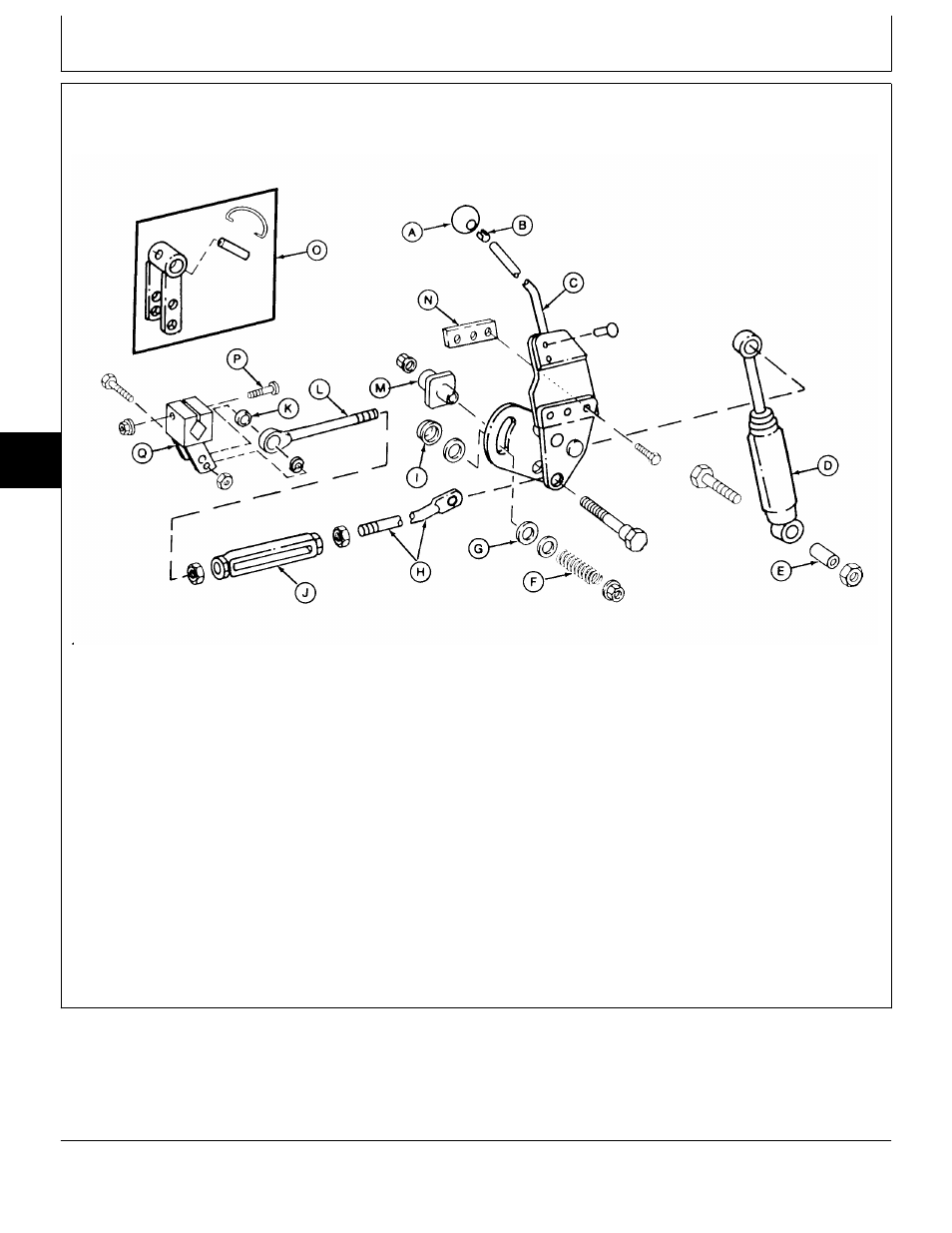
INSPECT AND REPAIR TRANSMISSION CONTROL LINKAGE—VERSION TWO (316 AND
318)
A—Knob
F—Compression Spring
K—Spacer
P—Cap Screw (Later Models)
B—Clip
G—Friction Disc (2 used)
L—Eyebolt
Q—Swashplate Arm (Later
C—Speed Control Lever
H—Speed Control Rod
M—Guide
Models)
D—Shock Absorber
I—Spacer
N—Weld Nut
E—Spacer
J—Turnbuckle
O—Swashplate Arm
Assembly (Early Models)
1. Remove belly screen, fender deck and fuel tank.
2. Remove engine side panels, battery and battery
base.
3. Remove right-hand pedestal side panel.
4. Inspect linkage for wear or damage. Replace parts
as necessary.
5. Adjust hydrostatic lever friction. (See procedure in
Section 250, Group 15.)
6. Later Models; After connecting swashplate arm (Q)
to transmission control shaft, tighten cap screw (P) to
60 N·m (44 lb-ft).
7. Adjust neutral return linkage. (See procedure in
Section 250, Group 15.)
M77908
-UN
-13MAR95
MX,15905010,2 -19-08MAY95
Transmission Control Linkage/Inspect and Repair Control Linkage
TM1590 (17MAY95)
50-10-2
316, 318 & 420 Lawn and Garden Tractors
020895
50
10
2