John Deere 318 User Manual
Page 245
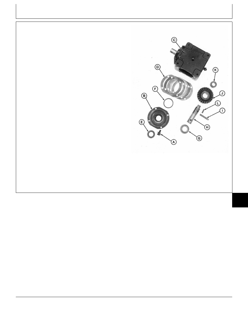
19. Install key (L) and bevel gear (J), shoulder end first,
onto shaft (H).
20. Align holes in bevel gear and shaft and install spring
pin (I).
21. Press bearing cone (K) on shaft with small O.D.
facing away from bevel gear (J). Install bearing until
seated.
22. Slide bearing cone (G) onto other end of input shaft
(H).
IMPORTANT: Do not press seal in until seated or
bottomed out. Seal will become
damaged and will leak.
23. Press new seal (E) into cap (B) until seal is flush
with first recess in bottom of cap.
24. Install new bearing cup (F), if removed, using a
driver set.
25. Apply multipurpose grease to lip of seal.
A—Cap Screw and Lock G—Bearing Cone
Plate (4 used)
H—Input Shaft
Input Shaft Side
B—Cap
I—Spring Pin
C—Gear Case
J—Bevel Gear
D—Shims (as required)
K—Bearing Cone
E—Seal
L—Key
F—Bearing Cup
M77329
-UN
-24FEB95
MX,15908015,17 -19-29MAR95
Mower Gear Case Repair/Early 60-Inch Mower (Curtis)
TM1590 (17MAY95)
80-15-17
316, 318 & 420 Lawn and Garden Tractors
020895
80
15
17