John Deere 318 User Manual
Page 307
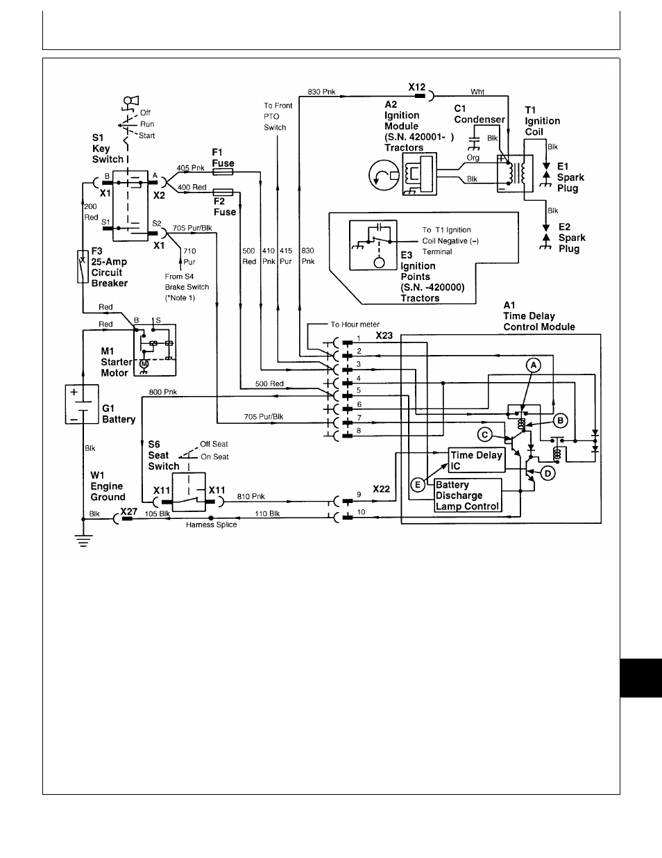
A—TDC Ignition Relay
C1—Condenser
G1—Battery
X12—Engine Harness 3-Pin
Contacts
(S.N. 420001— )
M1—Starter Motor
Connector
B—TDC Ignition Relay Coil
E1—Spark Plug
S1—Key Switch
X22—TDC Module 2-Pin
C—Switch Transistor
E2—Spark Plug
S6—Seat Switch
Connector
D—Time Delay Switch
E3—Ignition Points
T1—Ignition Coil
X23—TDC Module 8-Pin
Transistor
(S.N. —420000)
W1—Engine Ground
Connector
E—Time Delay IC (Internal
F1—20 Amp Fuse
X1—Key Switch 5-Pin
X27—Single Point Ground
Circuit)
F2—2 Amp Fuse
Connector
1-Pin Connector:
A1—Time Delay Control
(Early Machines)
X2—Key Switch 1-Pin
316 (S.N. 596121— )
(TDC) Module
3 Amp Fuse
Connector
318 (S.N. 600305— )
A2—Ignition Module
(Later Machines)
X11—Seat Switch 2-Pin
420 (S.N. 595881— )
(S.N. 420001— )
F3—25 Amp Circuit Breaker
Connector
NOTE: 1. For machines 316 (S.N. —596120), 318
(S.N. —600304) and 420 (S.N. —595880),
brake switch (S4) is not used. Interlock
current flow to transistor (C) comes from
transmission neutral start switch (S5).
NOTE: 2. The illustration shows ground circuit for
machines (S.N. 475001— ). For machines
(S.N. —475000), the blk wire from the TDC
module 2-pin connector terminates (grounds)
at the right pedestal panel.
M77922
-19
-04MAR95
MX,159024020,4 -19-16MAY95
Component Location and Operation/Theory of Operation
TM1590 (17MAY95)
240-15-5
316, 318 & 420 Lawn and Garden Tractors
020895
240
15
5