Disassemble and inspect drive shaft – John Deere 318 User Manual
Page 127
N
CAUTION: To avoid injury from escaping fluid
under pressure, stop engine and relieve the
pressure in the system before disconnecting or
connecting hydraulic or other lines. Tighten all
connections before applying pressure.
NOTE: Fender deck and fuel tank removed for
photographic purpose only.
7. On 318; Remove hydraulic lines (A) from control valve
as necessary to gain clearance for drive shaft to be
pulled forward from the transmission input shaft.
8. Remove drive shaft from tractor.
9. Installation is done in the reverse order of removal.
• Before installing drive shaft, apply MPG-2
®
Multi-Purpose Polymer Grease on splines of transmission
input shaft.
• Apply multipurpose grease to lubrication fittings.
• Bleed hydraulic system. (See procedure in Section 270,
Group 20.)
TORQUE SPECIFICATIONS
Drive Shaft Cap Screws
Flange-to-Engine . . . . . . . . . . . . . . . . . . . . . . 27 N·m (20 lb-ft)
Clamping Yoke-to-Transmission
Pump Shaft . . . . . . . . . . . . . . . . . . . . . . . . . . 60 N·m (44 lb-ft)
X9811
-UN
-23AUG88
M43707
-UN
-12JAN90
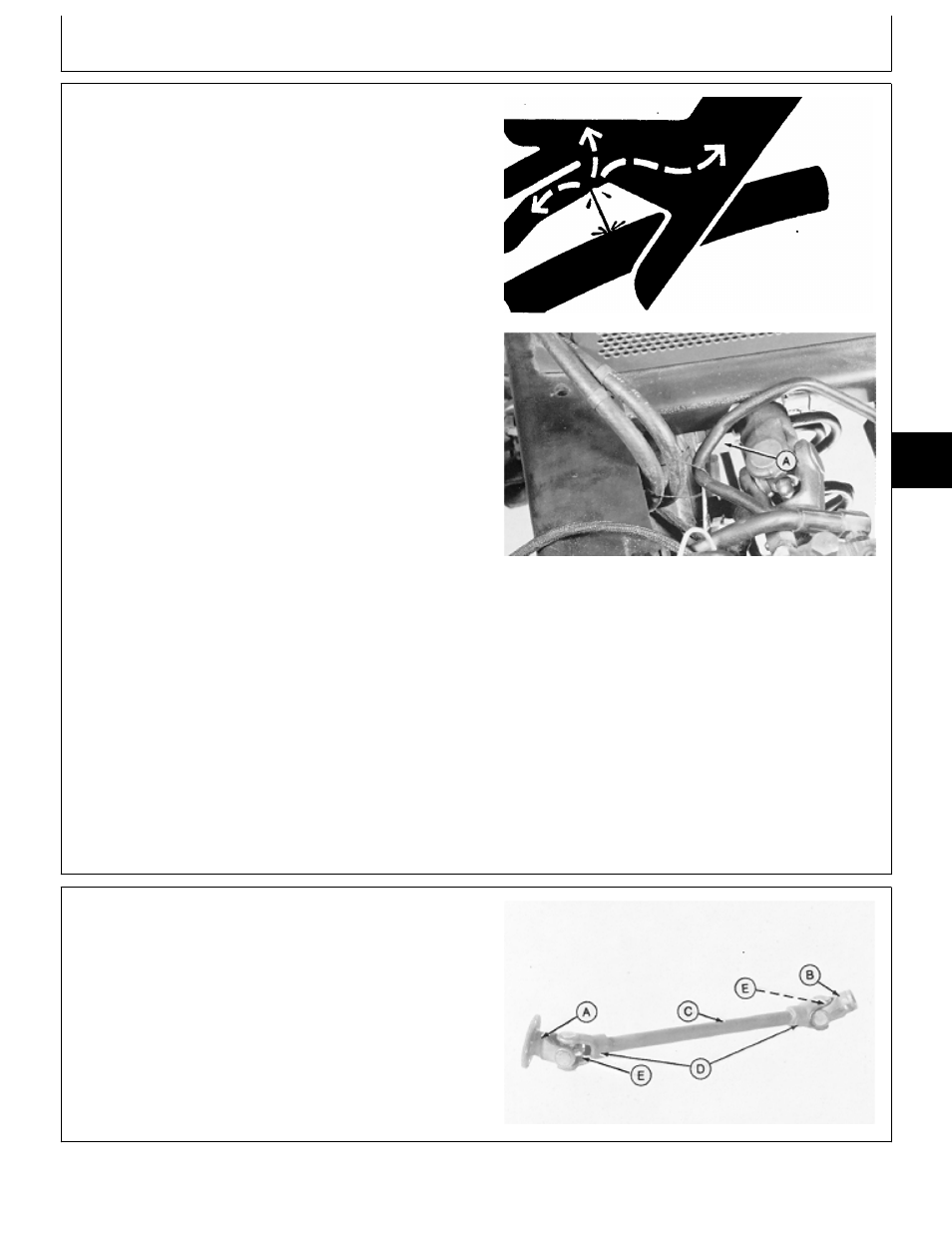
DISASSEMBLE AND INSPECT DRIVE SHAFT
1. Inspect flanged yoke (A), splined yoke (B), shaft (C),
end yokes (D) and cross and bearing assembly (E) for
cracks, wear, and bending.
A—Flanged Yoke
B—Splined Yoke
C—Shaft
D—End Yoke (2 used)
E—Cross and Bearing Assembly (2 used)
M43747
-UN
-12JAN90
MX,15905025,3 -19-07MAR95
MX,15905025,7 -19-20JAN95
Drive Shaft/Disassemble and Inspect
TM1590 (17MAY95)
50-25-3
316, 318 & 420 Lawn and Garden Tractors
020895
50
25
3