Disassemble and inspect charge pump – John Deere 318 User Manual
Page 63
NOTE: Transmission is removed for photographic
purpose only.
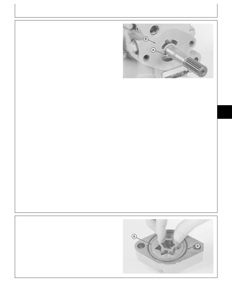
4. Remove pin (A). Inspect pin for straightness and
rounded ends. Replace if necessary.
5. Inspect machined surface (B) of transmission for
severe scoring. If scoring is noted replace transmission.
6. Make repairs as necessary. (See Disassemble,
Inspect and Assemble Charge Pump.)
7. Installation is done in the reverse order of removal.
• Apply clean John Deere Low Viscosity HY-GARD
®
oil
on all internal components.
• Apply petroleum jelly to pin (A) (to hold in place) and
lip of oil seal.
IMPORTANT: Tape end of transmission input shaft to
prevent seal damage during charge
pump installation.
• Apply tape around end of transmission input shaft.
• Install charge pump onto shaft. Turn pump until flat
side of casting is on relief valve side.
• Install mounting cap screws and tighten to 70 N·m (52
lb-ft).
• Remove tape from shaft and apply MPG-2
®
Multi-Purpose Polymer Grease on splines.
M36084
-UN
-29AUG88
DISASSEMBLE AND INSPECT CHARGE
PUMP
1. Remove inner ring and rotor ring (A).
2. Remove O-ring (B).
M36085
-UN
-29AUG88
MX,15905005,3 -19-07MAR95
MX,15905005,4 -19-23FEB95
Transmission/Charge Pump
TM1590 (17MAY95)
50-05-3
316, 318 & 420 Lawn and Garden Tractors
020895
50
05
3