John Deere 318 User Manual
Page 240
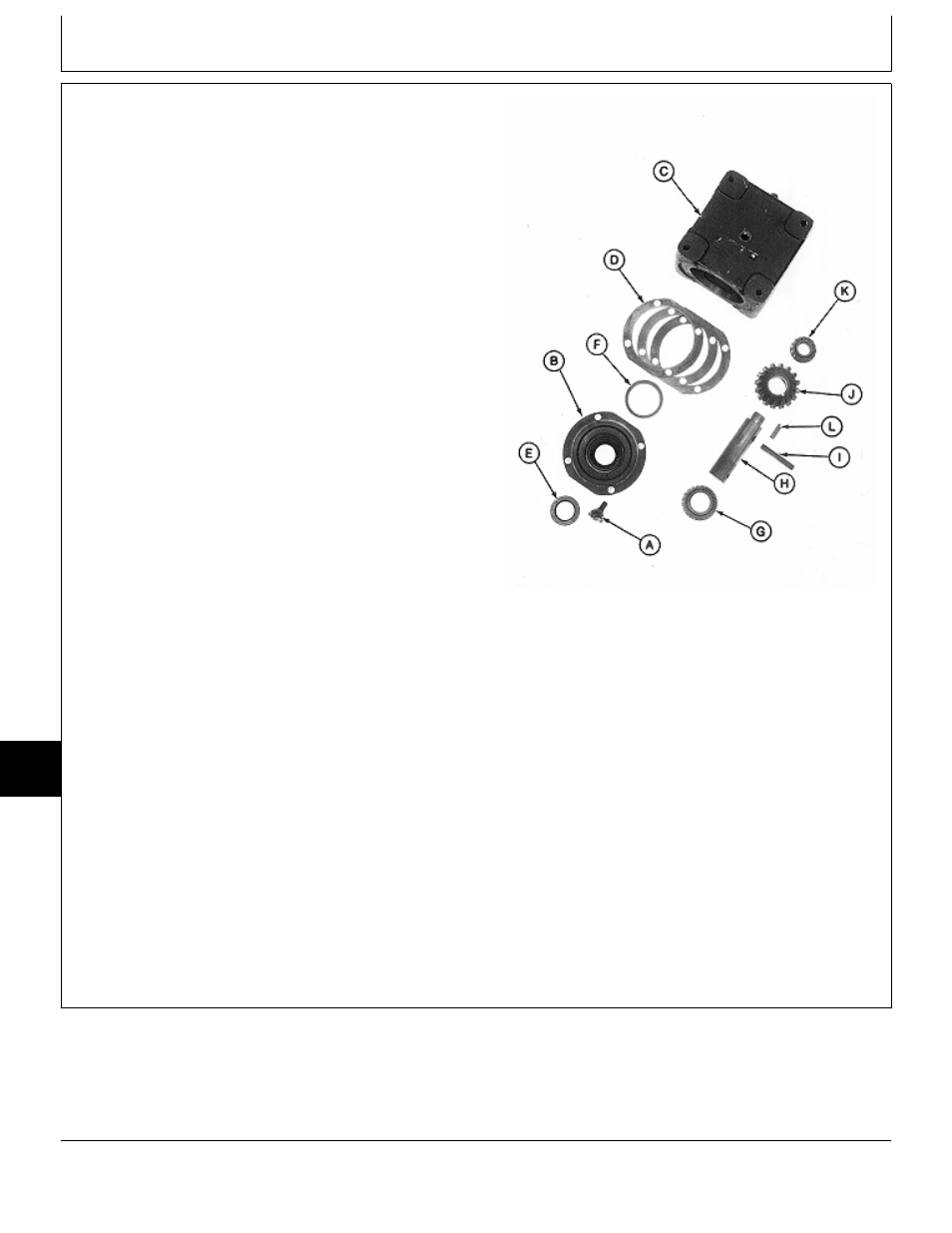
13. Remove four cap screws and lock plates (A).
14. Remove cap (B) and output shaft assembly from
gear case (C).
15. Remove shims (D) and output shaft assembly from
cap (B).
16. Pry out seal (E).
NOTE: Bearing cup is press-fit in cap. Remove bearing
cup only if replacement is necessary.
Bearing cone (K) is press-fit on input shaft.
Bearing cones and cups (one in gear case
housing) are matched and must be replaced as
complete assemblies.
17. Inspect bearing cup (F) for wear or damage. Replace
if necessary.
IMPORTANT: Remove bearing cups using a press
and driver disk, if possible. Using a
punch and hammer can damage cap.
Use only if necessary.
Output Shaft Side
18. Remove bearing cup (F) using a press and driver set
or punch and hammer.
A—Cap Screw and Lock Plate (4 used)
19. Slide bearing cone (G) off of output shaft (H).
B—Cap
C—Gear Case
D—Shims (as required)
20. Remove spring pin (I) using a punch and hammer.
E—Seal
F—Bearing Cup
21. Press shaft (H) from bevel gear (J) and bearing cone
G—Bearing Cone
(K).
H—Output Shaft
I—Spring Pin
J—Bevel Gear
22. Remove key (L).
K—Bearing Cone
L—Key
M77330
-UN
-24FEB95
MX,15908015,13 -19-13MAR95
Mower Gear Case Repair/Early 60-Inch Mower (Curtis)
TM1590 (17MAY95)
80-15-12
316, 318 & 420 Lawn and Garden Tractors
020895
80
15
12