John Deere 318 User Manual
Page 231
7. Press on threaded end of input shaft (C) to remove
seal (A) and input shaft assembly from pillow block (I).
NOTE: Bearing cone is press-fit on input shaft. Remove
bearing only if replacement is necessary.
Bearing cups are press-fit in pillow block.
Remove cups only if replacement is necessary.
Bearing cones and cups are matched and must
be replaced as complete assemblies.
8. Inspect bearing cone (D) and cups (G and H) for wear
or damage. Replace as necessary.
9. Remove snap ring (B) and press input shaft (C) from
bearing (D).
10. Remove O-ring (E) and snap ring (F).
IMPORTANT: Remove bearing cups using a press
and driver disk, if possible. Using a
punch and hammer can damage pillow
block. Use only if necessary.
11. Remove bearing cups (G and H) using a press and
driver set or punch and hammer.
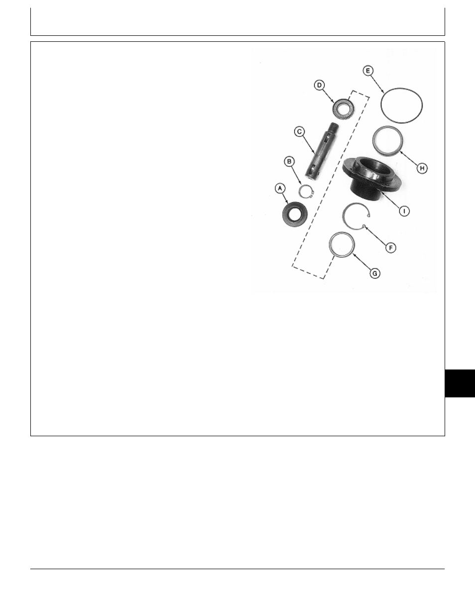
Input Shaft Assembly
A—Seal
B—Snap Ring
C—Input Shaft
D—Bearing Cone
E—O-Ring
F—Snap Ring
G—Bearing Cup
H—Bearing Cup
I—Pillow Block
M77318
-UN
-24FEB95
MX,15908015,3 -19-13MAR95
Mower Gear Case Repair/50-Inch Mower
TM1590 (17MAY95)
80-15-3
316, 318 & 420 Lawn and Garden Tractors
020895
80
15
3