John Deere 318 User Manual
Page 334
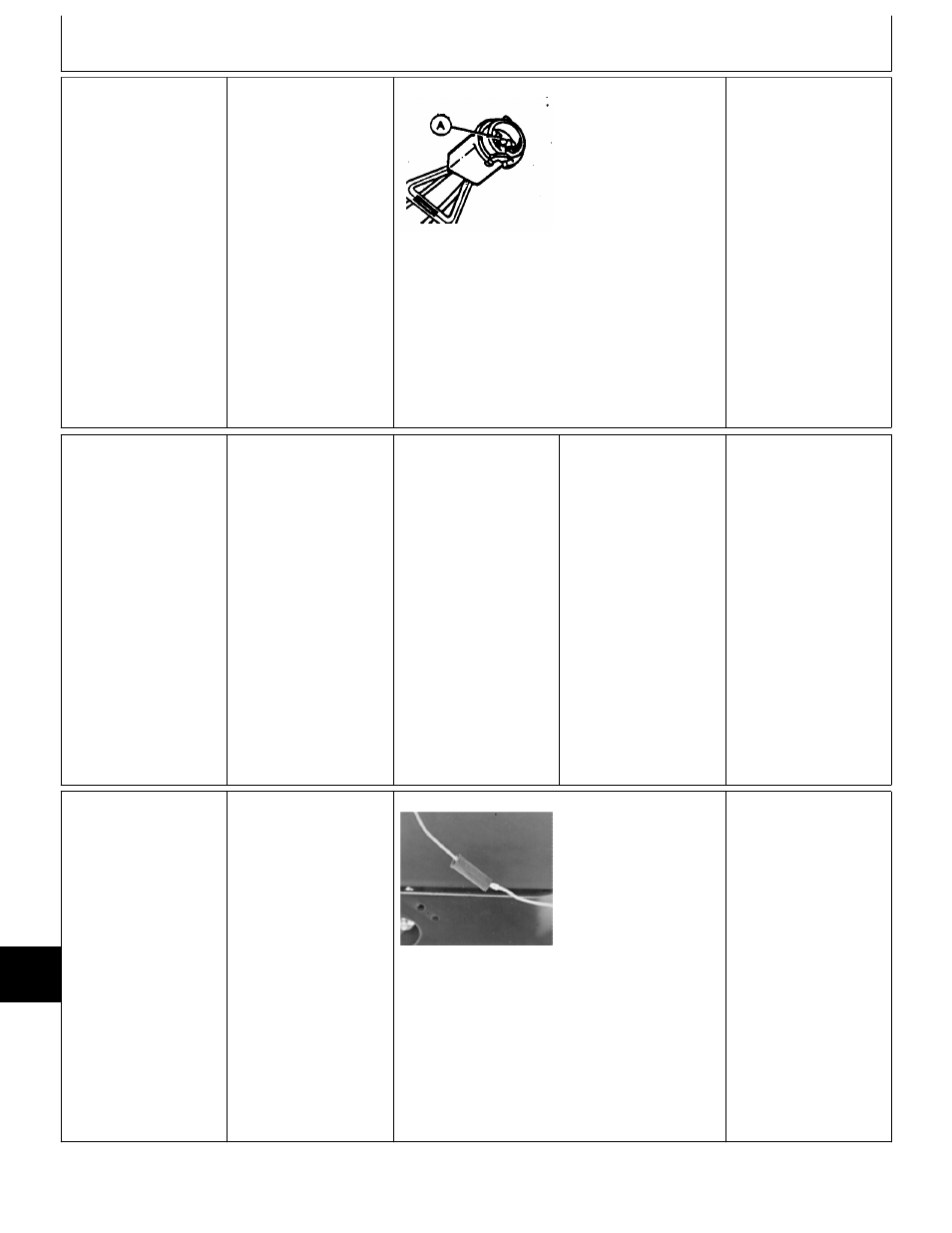
4a
PTO Lamp Test
Remove battery base to
access instrument
panel.
Disconnect PTO lamp
socket.
Remove and check
bulb.
M36643 -UN-29AUG88
If bulb is good, check
for continuity between
black wire at contact
(A) and ground.
CONTINUITY: Replace
blue wire between PTO
switch and bulb socket.
Repair or replace wire
as necessary, then GO
TO
Å
, Group 05.
NO CONTINUITY:
Repair or replace
ground wire as
necessary, then GO TO
Å
, Group 05.
4b
PTO Lamp Diode
Test
NOTE: Diodes are
designed to allow
current flow in one
direction only.
Remove battery base to
access instrument
panel.
Remove PTO lamp
socket.
Remove bulb.
Check diode with
ohmmeter or continuity
tester. If using a digital
meter, use diode check
position on meter.
Check for continuity
across terminals of bulb
socket. Reverse leads
and check again.
LOOK: There should be
continuity in one
direction only.
CONTINUITY ONE
DIRECTION ONLY:
Circuit probably has an
intermittent short.
Check all connections
and grounds, then GO
TO
Ò
, Group 25.
CONTINUITY BOTH
DIRECTIONS OR NO
CONTINUITY: Replace
diode.
4c
PTO Voltage Test
at Clutch
Connector
Remove right-hand
engine side panel.
Install jumper wire
across seat switch
connector or have
someone sit on seat.
Turn key switch to RUN
position.
Move PTO switch to
ON position.
M55084 -UN-09DEC89
NOTE: Machines
(S.N. —475000)
shown. Later machines
use a 2-pin connector.
Check for voltage at
blue lead of PTO clutch
connector.
VOLTAGE: GO TO
4d
NO VOLTAGE: GO TO
4e
MX,159024025,57-19-16MAY95
MX,159024025,58-19-16MAY95
MX,159024025,59-19-16MAY95
Electrical System Diagnosis/PTO Clutch and Lamp Tests
TM1590 (17MAY95)
240-20-22
316, 318 & 420 Lawn and Garden Tractors
020895
240
20
22